<ENGLISH>
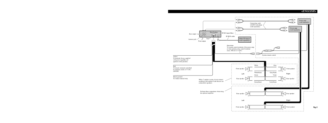
| This Product |
Rear output |
|
Antenna jack | Fuse |
| |
| Front output |
Connecting cords with RCA pin plugs (sold separately)
Power amp (sold separately)
Power amp (sold separately)
Yellow
To terminal always supplied with power regardless of ignition switch position.
Red
To electric terminal controlled by ignition switch (12 V DC) ON/OFF.
Blue/white
To system control terminal of the power amp or
System remote control
White | Gray |
+ |
|
Front speaker |
|
≠ |
|
White/black | Gray/black |
Left | Violet |
Green |
+
Front speaker
≠
Right
Black (ground)
To vehicle (metal) body.
With a 2 speaker system, do not connect anything to the speaker leads that are not connected to speakers.
Perform these connections when using the optional amplifier.
+
Rear speaker
≠
Green/blackViolet/black
+
Rear speaker
≠
Left
+
Front speaker
+
Rear speaker
≠
+
Rear speaker
≠
Right
+
Front speaker | Fig. 2 |
≠ | ≠ |