r

I

excellent high frequency characteristicscompara-

ble lo those of a small-signaltransistor.Further-

more,becanselhere is no time clonstantin the NFB

I

circuit ir-rthe lorv-frecluencyregion, amplification

is possibiedorvn to DC (DC inputs will be cut off,

hor,vever,by the input couplingcapacitor).

r

'I'he


circuit featuresdescribedaboveprovide an

extremely wide polver frequency range (60W

r

+ 60W, 101-lzto ZOkHz,THD 0.005Va,Bdl).

High SpeedBiasServocontrolCircuit


By operating the power stageonly within the

active region (no possiblecut-off) and with mini-

r

mr-rmidle current, the high speedbiasservocontrol


circuit prevents the generation of switching dis-


tortion and reducesheaf loss.


T

OperatingPrinciple


Since idle current flows through normal classB

r

SI)PPporver stages(seeFig. 4-10) when no signal

is appliecl,the DC level is shifted by D and VR by

a fixed amount (w'itirthe voltageacrosspoints X

anclY sen'ingas a bias).The voltagesacrosspoints

X and Z, and Z

and Y at this time will be equal.

T

When the positve portion of a signalis applied to

this circuit, the porver stagecurrent on the NPN

side is increased,and the voltage(Vn1) acrossboth

T

ends of RB1 also heing increased,resultingin the

voitage across point X and Z being increased.

However, since the voltage acrosspoints X and Y

is practically constant, the voltage across points

I

Z anrl Y (PNP power stagebias) will be decreased,

resultingin the PNPpower stagebeingcut off.

'I'he


high speed bias servocontrol circuit in-

f,

creasesthe voltage acrosspoints X and Y by the

sameamount as the voltageincreaseacrosspoints

X and Z, thereby cancellingthe voltage decrease

acrosspoinls Z

and

Y,

and

preventing

the PNP

polver


F


stagefrom beingcut off.


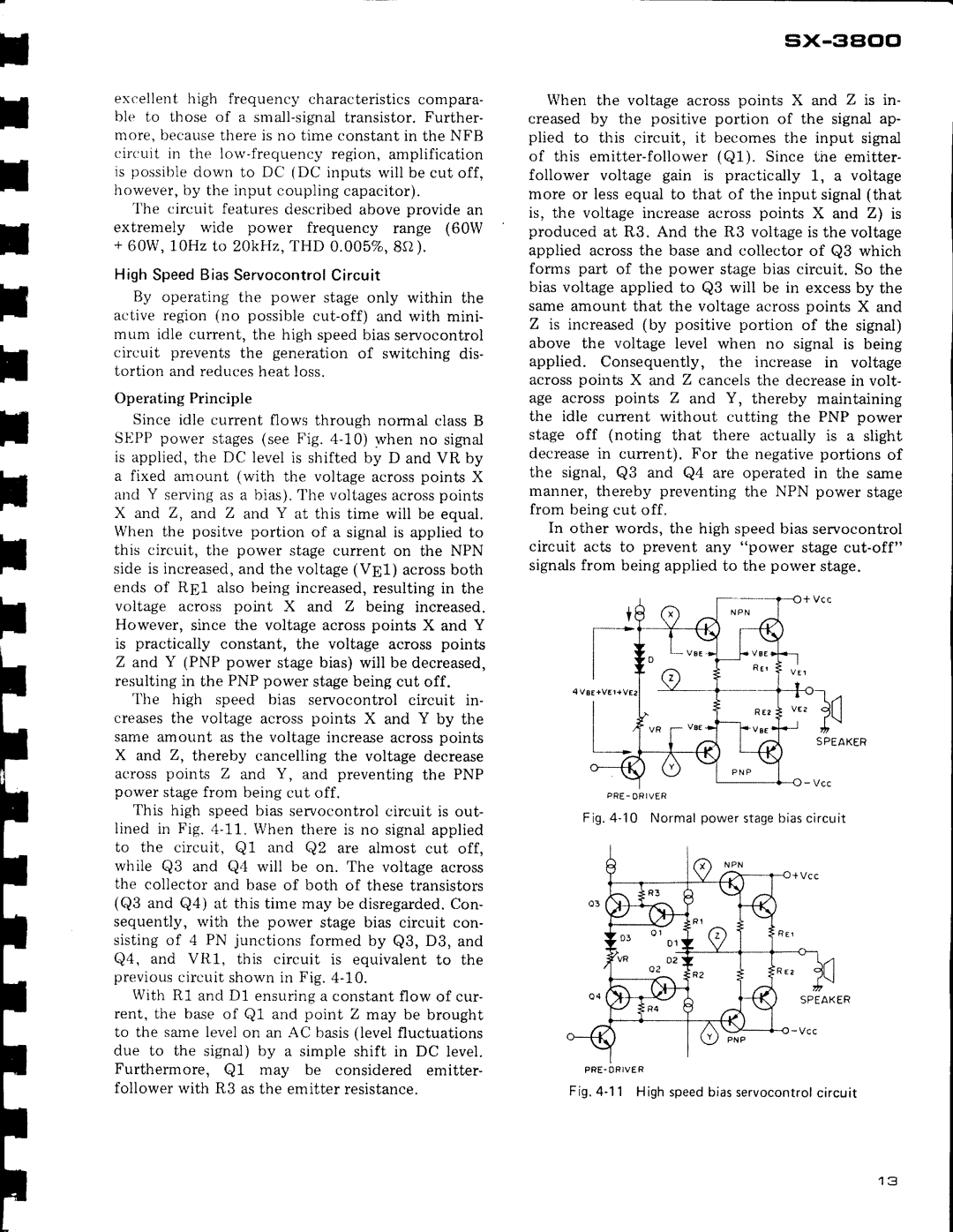
This high speedbias servocontrolcircuit is out-

lined in Fig. 4-11.lVhen thereis no signalapplied

to the crrcuit, Q1 and Q2 are almost cut off,

while Q3 and Q4 u'illbe on. The voitage across

t

fhe collector and baseof both of thesetransistors

(Q3 and Q4) at this time may be disregardedCon.-

sequently, rvith the power stagebias circuit con-

I

sistingof ,trPN junctions formed by Q3, D3, and

Q4, and VR1. this circuit is equivalent to the

previous


With circuil shownin Fig.4-10.


t


R1 and D1 ensuringa constantflow of cur-

rent, the baseof Q1 and point Z may be brought

to the samelevelon an AC basis(levelfluctuations

due to the signal) by a simple shift in DC level.

F

Furthermore, Qf

may

be

considered emitter-

follower lvitli R3 asthe emitter resistance.

F


F


sx-3aclo

When the voltage acrosspoints X and Z is in- creased by tl'repositive portion of the signal ap- plied to this circuit, it becomesthe input signal of this emitter-follower (Q1). Since the emitter- follower voltage gain is practically 1-, a voltage more or lessequal to that of the input signal(that is, the voltage increaseacrosspoints X and Z) is produced at R3. And the R3 voltageis the voltage applied acrossthe baseand collector of QB which forms part of the power stage bias circuit. So the bias voltage applied to Q3 will be in excessby the sameamount that the voltageacrosspoints X and

Zis increased(by positive portion of the signal) above the voltage level when no signal is being applied. Consequently, the increase in voltage acrosspoints X and Z cancelsthe decreasein volt- age across points Z and Y, thereby maintaining the idle current without cutting the PNP power stage off (noting that there actually is a slight decreasein current). For the negativeportions of the signal, Q3 and Q4 are operated in the same rnanner,thereby preventing the NPN power stage from beingcut off.

In other words, the high speedbiasservocontrol circuit acts to prevent any "poler stagecut-off"

signalsfrom beingappliedto the polyer stage.

P R E - O R I V E R

Fig .4 - 'l0 Normalpowerstagebiascircuit

P F E . O R I V E R

Fig .4 - 11 Highspeedbiasservocontrolcircuit

I J

Page 13
Image 13
Pioneer SX-3800 manual Excellent high frequency characteristicscompara, Ble lo those of a small-signaltransistor.Further

SX-3800 specifications

The Pioneer SX-3800 is a classic stereo receiver that emerged in the late 1970s, embodying the high-fidelity audio aspirations of its time. As part of Pioneer’s widely respected SX series, the SX-3800 is hailed for its exceptional sound quality, robust construction, and an array of features that cater to both audiophiles and casual listeners alike.

One of the SX-3800's standout characteristics is its power output. It delivers a solid 80 watts per channel into 8 ohms, making it capable of driving a variety of speaker systems with ease. This ensures a dynamic audio experience, with clear highs, rich midrange, and deep bass. The receiver also exhibits low total harmonic distortion (THD) ratings, which means the sound produced is clean and faithful to the original recording.

The SX-3800 is equipped with a high-quality AM/FM tuner, which is known for its excellent sensitivity and selectivity. Featuring a large analog dial, it allows users to effortlessly dial into their favorite stations while the signal strength meter helps in fine-tuning the reception. This tuner is complemented by Pioneer’s proprietary Auto-Seek tuning function, making it easier for users to find and lock onto stations.

In terms of connectivity, the SX-3800 comes with several inputs and outputs, including phono, tape, aux, and multiple speaker outputs, offering flexibility for various audio setups. Additionally, the built-in phono preamp ensures that vinyl lovers can connect their turntables with ease, preserving the rich detail and warmth that analog sources are known for.

Another technological highlight of the SX-3800 is its inclusion of a loudness control feature, which allows users to enhance the low and high frequencies at lower volume levels. This feature is particularly useful for late-night listening or in quieter environments where detail is essential but loudness is not an option.

With its solid construction, vintage aesthetics, and a beautiful wood finish, the Pioneer SX-3800 not only performs well but also adds a classic touch to any audio setup. Its blend of features, performance, and timeless design continues to make it a desirable component in the world of vintage audio equipment. Collectors and enthusiasts appreciate the SX-3800 not just for its sound quality but also for its enduring legacy in the rich history of audio technology.