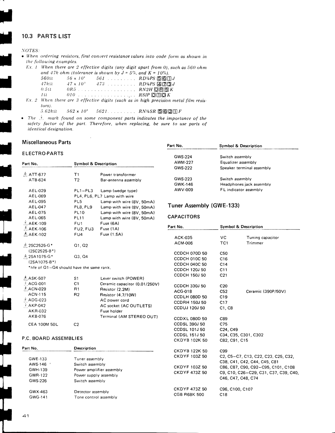
SX-3800 specifications
The Pioneer SX-3800 is a classic stereo receiver that emerged in the late 1970s, embodying the high-fidelity audio aspirations of its time. As part of Pioneer’s widely respected SX series, the SX-3800 is hailed for its exceptional sound quality, robust construction, and an array of features that cater to both audiophiles and casual listeners alike.One of the SX-3800's standout characteristics is its power output. It delivers a solid 80 watts per channel into 8 ohms, making it capable of driving a variety of speaker systems with ease. This ensures a dynamic audio experience, with clear highs, rich midrange, and deep bass. The receiver also exhibits low total harmonic distortion (THD) ratings, which means the sound produced is clean and faithful to the original recording.
The SX-3800 is equipped with a high-quality AM/FM tuner, which is known for its excellent sensitivity and selectivity. Featuring a large analog dial, it allows users to effortlessly dial into their favorite stations while the signal strength meter helps in fine-tuning the reception. This tuner is complemented by Pioneer’s proprietary Auto-Seek tuning function, making it easier for users to find and lock onto stations.
In terms of connectivity, the SX-3800 comes with several inputs and outputs, including phono, tape, aux, and multiple speaker outputs, offering flexibility for various audio setups. Additionally, the built-in phono preamp ensures that vinyl lovers can connect their turntables with ease, preserving the rich detail and warmth that analog sources are known for.
Another technological highlight of the SX-3800 is its inclusion of a loudness control feature, which allows users to enhance the low and high frequencies at lower volume levels. This feature is particularly useful for late-night listening or in quieter environments where detail is essential but loudness is not an option.
With its solid construction, vintage aesthetics, and a beautiful wood finish, the Pioneer SX-3800 not only performs well but also adds a classic touch to any audio setup. Its blend of features, performance, and timeless design continues to make it a desirable component in the world of vintage audio equipment. Collectors and enthusiasts appreciate the SX-3800 not just for its sound quality but also for its enduring legacy in the rich history of audio technology.

