KV-T29SN81
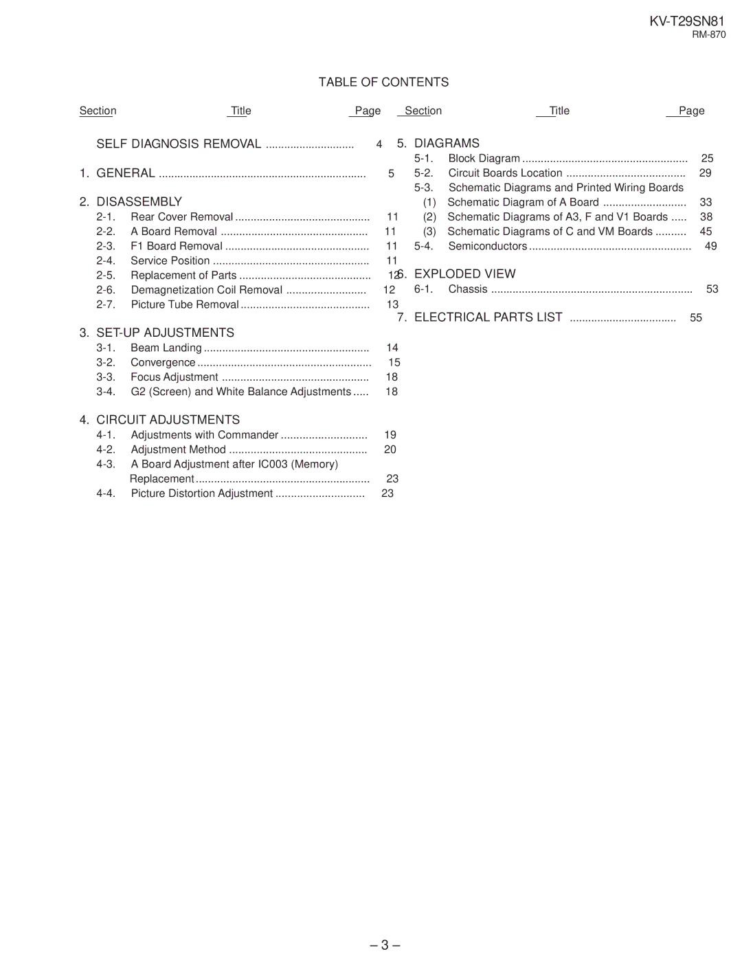
TABLE OF CONTENTS
SectionTitlePage SectionTitlePage
SELF DIAGNOSIS REMOVAL | 4 | 5. DIAGRAMS |
| |
|
| Block Diagram | 25 | |
1. GENERAL | 5 | Circuit Boards Location | 29 | |
|
| Schematic Diagrams and Printed Wiring Boards |
| |
2. DISASSEMBLY |
| (1) Schematic Diagram of A Board | 33 | ||
Rear Cover Removal | 11 | (2) Schematic Diagrams of A3, F and V1 Boards | 38 | ||
A Board Removal | 11 | (3) Schematic Diagrams of C and VM Boards | 45 | ||
F1 Board Removal | 11 | Semiconductors | 49 | ||
Service Position | 11 | 6. EXPLODED VIEW |
| ||
Replacement of Parts | 12 |
| |||
Demagnetization Coil Removal | 12 | Chassis | 53 | ||
Picture Tube Removal | 13 | 7. ELECTRICAL PARTS LIST |
| ||
|
|
| 55 | ||
3. |
|
|
|
| |
Beam Landing | 14 |
|
|
| |
Convergence | 15 |
|
|
| |
Focus Adjustment | 18 |
|
|
| |
18 |
|
|
| ||
4. CIRCUIT ADJUSTMENTS |
|
|
|
| |
Adjustments with Commander | 19 |
|
|
| |
Adjustment Method | 20 |
|
|
| |
|
|
|
| ||
| Replacement | 23 |
|
|
|
Picture Distortion Adjustment | 23 |
|
|
| |
– 3 –
