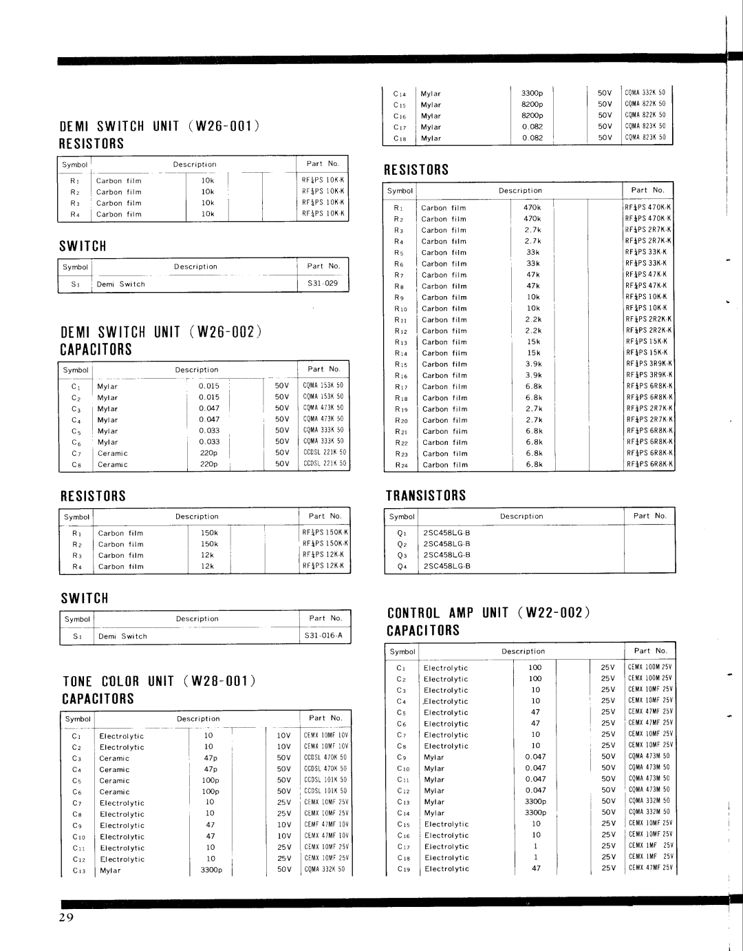
D t Msl w t T cuHN r T( w 2 6 - 0 0 1 )

RTSIST(]RS

C r a

M y l a r

5 0 v 0QMA332K5o

C l 5

Mylar

5 0 v cQuA822l(50


lVylar

5 0 v

cQllA822l(50

C r 7

M y l a r

5 0 v

cQMA823K50

C r e

N,'lylar

5 0 v coMA823(50

S y m b o l


.,,0-'*,

D e s c r i p t i o n


P a r t N o

*

I

I

n;

I

T

-*


]-':'s

R :


C a r b o nf i l m


l O k


R F I P S1 0 KX

R r


c a r b o nf r l m

I

t o r I

I

I R f l P sl o K K

R a


C a r b o nf i r m

I

r o l


R F i P Sl O KK

SWITCH


Symbol


D e s c r i o t i o n


P a r t N o

S r


D e m i S w i t c h


s 31- 029

DrMtswrTcHl,JtirT(w26-002)

CAPACITORS

t.'

D e s c n p t i o n


P a r t N o

Svmbol


I


IMylar

0 . 0 1 5

T sov I 'QMAr53K50

C z

Mylar

0 . 0 1 5

sOV


cQl',iA153K50

!'

Mylar

o . M 7

5ov

I 0QMA473Kso

V 4

Mylar

o . M 7

5OV


cQlVlA473(50

C 5

Mylar

0 . 033

5ov

I

OQMA333(50

C 6

lvlylar

o . 033

50v

I

CQMA333K50

C 7

Ceramic

22Op

5 0 v c c D s2L2 l x5 0

C s

Ceramic

22Op

5OV

L CCDST221K50

RESIST(]RS

Symbol


D e s c r i p t i o n


R r

Carbon

l m

l.

470k

1

R z

Carbon

l m

+ton


R 3

Carbon

l m


2 . 7 k


R a

Carbon

l m


2 . 7k


R 5

Carbon

t m

I

33k

i

R 6

Carbon

l m

33k


R 7

Carbon

l m


47k


R s

Carbon

I m

L i ; l l

R s

Carbon

r l m


i:r


R i l

Carbon

I m


R r o

Carbon

i l m


R r z

Carbon

r l m


2 . 2 k


R r 3

Carbon

r l m


1 5 k


R r a

Carbon

r l m


1 5 k

I

R 1 5

Carbon

i l m

l l 3 l

R 1 6

Carbon

i l m

l s l l

R r r

Carbon

r l m

R r e

Carbon

I m

R r s

Carbon

t l m


2 . 7 k

i

R 2 0

Carbon

i l m


2 . 7k


Rz r

Carbon

r l m


3il


Rzz

Carbon

i l m

I


R 2 3

Carbon

r l m

o . e k


R2a

Carbon

r l m

I

o . an

P a r t N o .

R F } P S4 7 O K , K R F } P S4 7 O KK R F l P S2 R 7 K , K R F } P S2 R 7 K . K R F I P S3 3 ( K

R F I P S3 3 K . K RFiPS4 7K . K R F } P S4 7 K - K R F i P SlO K . K RFiPSI OK . K R F i P S2 R 2 K . K R F I P S2 R 2 K - K R F i P SI 5 K . K R F I P S1 5 K . K R F i P S3 R 9 K . K R F i P S3 R 9 K , X R F } P S6 R 8 K . K R F i P S6 R 8 KK R F } P S2 R 7 KK R F I P S2 R 7 K , K R F I P S6 R 8 K . K R F * P S6 R 8 K , K R F i P S6 R 8 K . K R F i P S6 R 8 KK

RESIST()RS

SymbolI

R r c a r b o n f r t m R z I C a r b o nf i l m

R . C a r b o nf r t m R + I c a r b o n t i l m

Descnption


]

Part No


1 5 o k


I


R F : P Sl5 0 KK

l 5 0 k


R F I P S1 5 0 KK

1 2 k


I R r i P Sl 2 K . K

r 2 k

I


I R F i P Sl2 K K

TRAI{SIST()RS

Symbol

D e s c r i p t i o n

P a r l N o

Q r

2SC458LGB


Q z

2SC458LG . B


Q :

2SC458LG . B


Q +

2SC458LG,B


SWITCH

S y m b o l


D e s c r i p t i o n

P a r t N o .

S l

D e m i S w i t c h


s 3 1 - 0 1 6 . A

c0tfTR0LAMPUl{lT(W22-002)CAPACITtlRS

Tt]NEC't)L(]RUNIT(W2B _ t]l1)

CAPACIT()RS

D e s c r i p t i o n

C r

E l e c t r o l y t i c

C z

E l e c t r o l y t i c

C a

E l e c t r o l y t i c

C a

. Electrolyti c

C 5

Electrolyti c

25V c t M Xl0 0 M2 5 v

25V ctMx100M25v

25V CEMXIOMF25V

25V CTMXIOMF25V

25V CIMX47MF25V

Symbol

C r

E l e c t r o l y t i c

C 2

E l e c t r o l y t i c

C a

C e r a m i c

C +

C e r a m i c

C s

C e r a m i c

C 6

C e r a m i c

C 7

E l e c t r o l y t i c

C 8

E l e c t r o l y t i c


E l e c t r o l y t i c

C r o

E l e c t r o l y t i c

C r r

E l e c t r o l y t i c

C t z

E l e c t r o l y t i c

C r :

N4yla r


N o


1 0 v


cE,iX10t\4Fl0V


1 0 v


CIMXIOMF]OV


50v


ccDsL470(50

47p

50v


ccDsl470K50

I O0p

50v


ccDst10lr(50

lOOp

50v

, c c D s1r0 l K5 0

1 0

25V

I cEr\l1XloMF25V

1 0

25V

cEt\,tx10t\rF25v

471 0 v cErllF47t\lFl0v

471 0 v ct]llx47r\4F10v

1 0

25V

I CEMXl0MF25V

1 0

25V

I ceuxrourzsv

33O00

5 0 v

I CQTVTA332K50

C 6

E l e c t r o l y t i c

C j

Elect rolyti c


E l e c t r o l y t i c

C e

lMylar

C r o

lvylar

C r r

lVylar

C 1 2

lMylar

C 1 3

Mylar

C 1 4

lMylar


E l e c t r o l y t i c

C t o

E l e c t r o l y t i c

C t t

E l e c t r oyl t i c

C l 8

E l e c t r o l y t i c

C t e

Electrolyti c

25V cEMX4iMF 25V

25V CEMXIOMF25V

25V CEMXIOMF25V

50v CQMA473M50

50v 0QMA473M50

50v 0QMA473M50

50v c0rvlA473M50

50v cQruA332M50

50v cQrt4A332rV50

25V I cEtxlor'25v.F

25V I CEMXloMF2sv

25V CEMXlMF 25V

25V CEMXIMF 25V

25V I CEMX47MF2sv

Page 30
Image 30
Pioneer SX-9000 service manual Msl w t T cuHN r T w 2 6 0 0, Rtsistrs, Switch, Traisistrs, TtNECtLRUNITW2B tl1

SX-9000 specifications

The Pioneer SX-9000 is a vintage receiver that was first introduced in the early 1970s, showcasing the high-fidelity audio technology that Pioneer was known for during that era. As a part of the SX-series receivers, the SX-9000 stood out for its impressive features, robust design, and high-quality sound reproduction, making it a coveted piece of audio equipment among audiophiles and collectors alike.

One of the key features of the SX-9000 is its powerful amplification capability. With a power output of 80 watts per channel at 8 ohms, it is capable of driving a wide range of speakers effectively, providing dynamic and clear sound at various volume levels. The receiver utilizes a transistor-based design, ensuring reliability and efficiency in sound delivery.

The SX-9000 also supports a range of tuning options, including FM stereo and AM bands, with an integrated multiplex decoder for enhanced stereo separation. Its switched capacitor AM/FM tuner is designed to provide precise frequency captures, minimizing distortion and improving overall sound quality. Additionally, the receiver features a glass front panel and analog tuning dial, reflecting the classic design aesthetics of the time.

Another notable characteristic is its extensive input options. The SX-9000 has multiple inputs, including auxiliary, phono, and tape, allowing users to connect a variety of audio sources such as turntables, cassette decks, and other components. The inclusion of a phono stage preamp makes it an excellent choice for vinyl enthusiasts, offering high-quality playback of records with minimal noise.

Equipped with tone control features, the SX-9000 allows users to adjust bass and treble to their liking, giving them greater control over their listening experience. The loudness function is another valuable addition, enhancing playback at lower volume levels, ensuring that sound remains rich and full.

Overall, the Pioneer SX-9000 is a testament to the company's commitment to producing high-quality audio equipment. Its blend of power, versatility, and classic design make it a lasting favorite for vintage audio lovers, maintaining a strong reputation decades after its release. The SX-9000 embodies the spirit of audio fidelity, making it a vital piece in the legacy of Pioneer receivers. Its features and capabilities continue to resonate with today's audiophiles, underlining its timeless appeal.