SX-9000 specifications
The Pioneer SX-9000 is a vintage receiver that was first introduced in the early 1970s, showcasing the high-fidelity audio technology that Pioneer was known for during that era. As a part of the SX-series receivers, the SX-9000 stood out for its impressive features, robust design, and high-quality sound reproduction, making it a coveted piece of audio equipment among audiophiles and collectors alike.One of the key features of the SX-9000 is its powerful amplification capability. With a power output of 80 watts per channel at 8 ohms, it is capable of driving a wide range of speakers effectively, providing dynamic and clear sound at various volume levels. The receiver utilizes a transistor-based design, ensuring reliability and efficiency in sound delivery.
The SX-9000 also supports a range of tuning options, including FM stereo and AM bands, with an integrated multiplex decoder for enhanced stereo separation. Its switched capacitor AM/FM tuner is designed to provide precise frequency captures, minimizing distortion and improving overall sound quality. Additionally, the receiver features a glass front panel and analog tuning dial, reflecting the classic design aesthetics of the time.
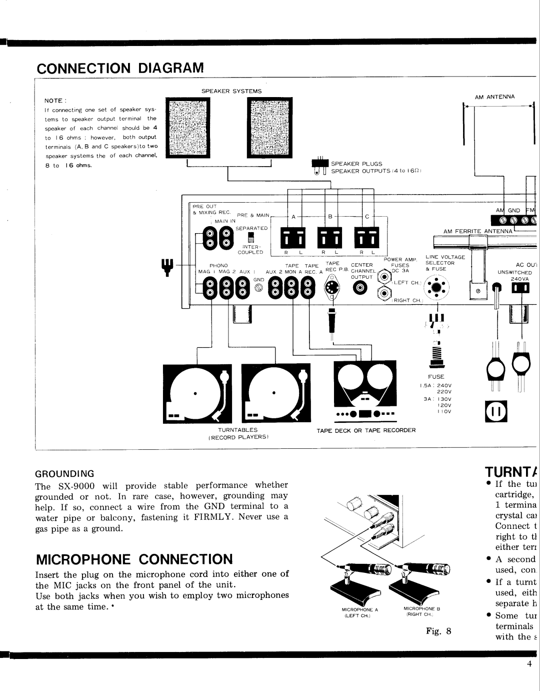
Another notable characteristic is its extensive input options. The SX-9000 has multiple inputs, including auxiliary, phono, and tape, allowing users to connect a variety of audio sources such as turntables, cassette decks, and other components. The inclusion of a phono stage preamp makes it an excellent choice for vinyl enthusiasts, offering high-quality playback of records with minimal noise.
Equipped with tone control features, the SX-9000 allows users to adjust bass and treble to their liking, giving them greater control over their listening experience. The loudness function is another valuable addition, enhancing playback at lower volume levels, ensuring that sound remains rich and full.
Overall, the Pioneer SX-9000 is a testament to the company's commitment to producing high-quality audio equipment. Its blend of power, versatility, and classic design make it a lasting favorite for vintage audio lovers, maintaining a strong reputation decades after its release. The SX-9000 embodies the spirit of audio fidelity, making it a vital piece in the legacy of Pioneer receivers. Its features and capabilities continue to resonate with today's audiophiles, underlining its timeless appeal.

