CONNECTIONS
CONNECTIONS TO Y OUR TV | 3. Next, set your TV to channel 3 or 4, whichever is not | ||
1. Remove your VHF antenna cable from the VHF ANT | used for commercial TV broadcasts in your area. Then | ||
|
| ||
terminal(s) on your TV set, and connect the cable to the | set | VHF CHANNEL SELECTOR on VP·1000 to the | |
same channel accordingly as shown in fig. 6. | |||
ANTENNA IN terminal(s) on Vp·l000. For twin·lead | |||
4. Plug | AC power cord for | ||
feeder antenna cable (300 ohms) prepare the wire leads | |||
socket (120V, 60Hz). This completes the standard con | |||
as shown in the left of fig. 4 and connect to the | |||
nection procedure for video and audio reproduction | |||
ANTENNA IN 300 ohms BAL terminals. For coaxial | |||
|
| ||
antenna cable (75 ohms), an F type plug must be fitted | through your TV . | ||
|
| ||
to the end of the cable, as shown in the right of fig. 4, in |
|
| |
order to connect it to the ANTENNA IN 75 ohms UN· |
|
| |
BA L terminal. |
|
| |
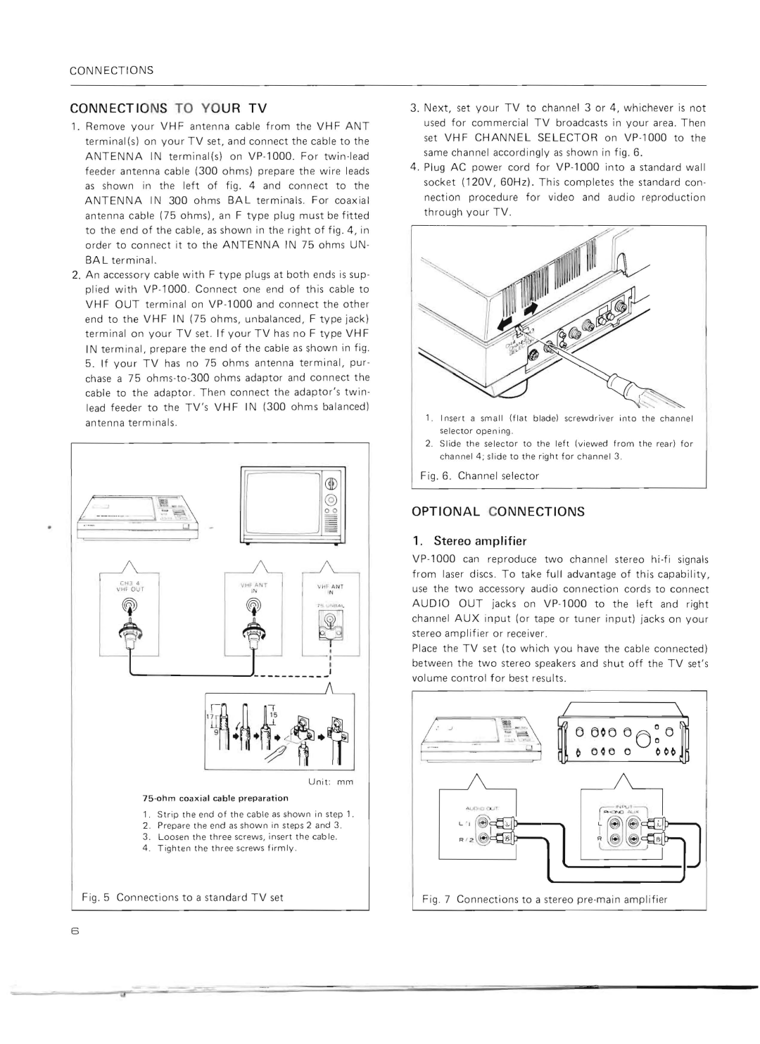
2.An accessory cable with F type plugs at both ends is sup· plied with VP·l000 . Connect one end of this cable to VHF OUT terminal on VP·l000 and connect the other end to the VHF IN (75 ohms, unbalanced, F type jack) terminal on your TV set. If your TV has no F type VHF IN terminal, prepare the end of the cable as shown in fig. 5. If your TV has no 75 ohms antenna terminal, pur· chase a 75 ohms·to·300 ohms adaptor and connect the cable to the adaptor. Then connect the adaptor's twin
lead feeder to the TV's VHF IN (300 ohms balanced) |
|
|
|
|
|
|
|
|
| |||||||||
antenna terminals. |
|
|
|
| 1. | I nsert a small (flat blade) screwdriver | into | the channel | ||||||||||
|
|
|
|
|
| selector open i ng. |
|
|
|
|
| |||||||
|
|
|
|
|
|
|
|
|
|
|
|
|
|
|
|
| ||
|
|
|
|
|
|
|
|
|
|
| 2 . Slide the selector to | the left (vi ewed | from | th e rear) | for | |||
|
|
|
|
|
|
|
|
|
| |||||||||
|
|
|
|
|
|
|
|
|
|
|
| channel 4 ; slide to the right for channel 3. |
|
|
| |||
|
|
|
|
|
|
|
|
|
|
| Fig.6. Channel selector |
|
|
|
| |||
J.~~ |
| O i |
|
|
|
|
|
|
| |||||||||
|
|
|
|
|
|
| ||||||||||||
|
|
|
|
|
|
|
|
|
| |||||||||
|
|
| 1. | Stereo amplifier |
|
|
|
|
| |||||||||
|
|
|
|
|
|
|
|
|
|
| OPTIONAL CONNECTIONS |
|
|
|
| |||
|
|
|
|
|
|
|
|
|
|
| Vp·l000 can reproduce two channel stereo | |||||||
|
|
|
|
|
|
|
|
|
|
| ||||||||
| CtD do |
|
|
|
|
|
|
|
| from laser discs. To take full advantage of this capability, | ||||||||
|
|
|
|
|
|
|
| |||||||||||
|
|
|
|
|
|
|
| use | the | two acce ss ory audio connection cords to connect | ||||||||
| \ 'HF | our |
|
|
|
|
|
|
| |||||||||
|
|
|
|
|
|
|
|
|
|
| AU D 10 | OUT jacks on | left and | right | ||||
|
|
|
|
|
|
|
|
|
|
| channel AUX input (or tape or tuner input) jacks on your | |||||||
|
|
|
|
|
|
|
|
|
|
| stereo amplifier or receiver. |
|
|
|
| |||
|
|
|
|
|
|
|
|
|
|
| Place the TV set (to which you have the cable connected) | |||||||
|
|
|
|
|
|
|
|
|
|
| between the two stereo speakers and shut off the TV set's | |||||||
|
|
|
|
|
|
|
|
|
|
| volume control for best results. |
|
|
|
| |||
/.i
Unit: mm
1.Strip the end of the cable as shown in step 1.
2.Prepare the end as shown in steps 2 and 3.
3.Loosen the three screws, insert the cable.
4 . Tighten th e three screws firmly.
Fig.5 Connections to a standard TV set
Fig.7 Connections to a stereo pre-main amplifier
6
