Connections
Connections
Connection Panel
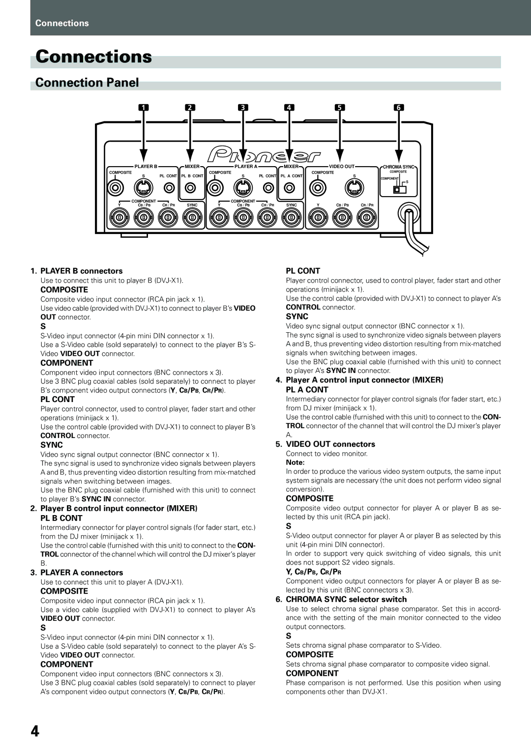
1 | 2 | 3 | 4 | 5 | 6 |
| PLAYER B |
| MIXER |
| PLAYER A |
| MIXER |
| VIDEO OUT | CHROMA SYNC |
COMPOSITE | S | PL CONT | PL B CONT | COMPOSITE | PL CONT | PL A CONT | COMPOSITE | COMPOSITE | ||
|
| S |
| S | COMPONENT | |||||
|
|
|
|
|
|
|
|
|
| |
|
|
|
|
|
|
|
|
|
| S |
| COMPONENT |
|
|
| COMPONENT |
|
|
|
|
|
Y | CB / PB | CR / PR | SYNC | Y | CB / PB | CR / PR | SYNC | Y | CB / PB | CR / PR |
1.PLAYER B connectors
Use to connect this unit to player B
COMPOSITE
Composite video input connector (RCA pin jack x 1).
Use video cable (provided with
S
Use a
COMPONENT
Component video input connectors (BNC connectors x 3).
Use 3 BNC plug coaxial cables (sold separately) to connect to player B’s component video output connectors (Y, CB/PB, CR/PR).
PL CONT
Player control connector, used to control player, fader start and other operations (minijack x 1).
Use the control cable (provided with
PL CONT
Player control connector, used to control player, fader start and other operations (minijack x 1).
Use the control cable (provided with
SYNC
Video sync signal output connector (BNC connector x 1).
The sync signal is used to synchronize video signals between players A and B, thus preventing video distortion resulting from
Use the BNC plug coaxial cable (furnished with this unit) to connect to player A’s SYNC IN connector.
4.Player A control input connector (MIXER)
PL A CONT
Intermediary connector for player control signals (for fader start, etc.) from DJ mixer (minijack x 1).
Use the control cable (furnished with this unit) to connect to the CON- TROL connector of the channel that will control the DJ mixer’s player A.
SYNC
Video sync signal output connector (BNC connector x 1).
The sync signal is used to synchronize video signals between players A and B, thus preventing video distortion resulting from
Use the BNC plug coaxial cable (furnished with this unit) to connect to player B’s SYNC IN connector.
2.Player B control input connector (MIXER)
PL B CONT
Intermediary connector for player control signals (for fader start, etc.) from the DJ mixer (minijack x 1).
Use the control cable (furnished with this unit) to connect to the CON- TROL connector of the channel which will control the DJ mixer’s player B.
5.VIDEO OUT connectors
Connect to video monitor.
Note:
In order to produce the various video system outputs, the same input system signals are necessary (the unit does not perform video signal conversion).
COMPOSITE
Composite video output connector for player A or player B as se- lected by this unit (RCA pin jack).
S
In order to support very quick switching of video signals, this unit does not support S2 video signals.
3.PLAYER A connectors
Use to connect this unit to player A
COMPOSITE
Composite video input connector (RCA pin jack x 1).
Use a video cable (supplied with
S
Use a
COMPONENT
Component video input connectors (BNC connectors x 3).
Use 3 BNC plug coaxial cables (sold separately) to connect to player A’s component video output connectors (Y, CB/PB, CR/PR).
Y, CB/PB, CR/PR
Component video output connectors for player A or player B as se- lected by this unit (BNC connectors x 3).
6.CHROMA SYNC selector switch
Use to select chroma signal phase comparator. Set this in accord- ance with the setting of the main monitor connected to the video output connectors.
S
Sets chroma signal phase comparator to
COMPOSITE
Sets chroma signal phase comparator to composite video signal.
COMPONENT
Phase comparison is not performed. Use this position when using components other than
4