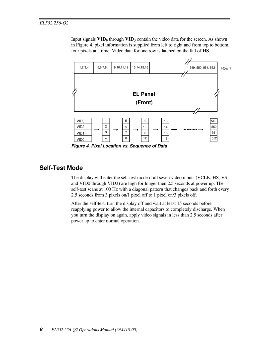
Input signals VID0 through VID3 contain the video data for the screen. As shown in Figure 4, pixel information is supplied from left to right and from top to bottom, four pixels at a time. Video data for one row is latched on the fall of HS.
1,2,3,4
5,6,7,8
9,10,11,12 13,14,15,16
549, 550, 551, 552
Row 1
EL Panel
(Front)
VID3 |
|
|
| 1 |
|
| 5 |
|
|
| 9 |
|
|
| 13 | |
VID2 |
|
|
| 2 |
|
| 6 |
|
|
| 10 |
|
|
| 14 | |
|
|
|
|
|
|
|
|
|
|
|
|
|
|
|
| |
VID1 |
|
|
| 3 |
|
| 7 |
|
|
| 11 |
|
|
| 15 | |
VID0 |
|
|
| 4 |
|
| 8 |
|
|
| 12 |
|
|
| 16 | |
|
|
|
|
|
|
|
|
|
|
|
|
|
|
|
| |
Figure 4. Pixel Location vs. Sequence of Data
549
550
551
552
Self-Test Mode
The display will enter the
After the
8