Method A represents sourcing the dimming input from a voltage source such as a DAC or analog op amp. The device should be powered from +5 Vdc such that the device’s output will not exceed the allowable input range of the dimming input.
Method B creates the dimming voltage from a potentiometer. The recommended value for the pot is from 10K to 100K ohms. If J2 pin 1 is used as the pot
Method C shows a simple strap which sets the display to maximum luminance. If the input is left unconnected, the input will be in the
Method D represents a CMOS or TTL logic gate, or a comparator to drive the backlight /DISABL input.
Method E shows an open collector device such as a bipolar transistor or FET.
Method F represents a switch or jumper.
In all cases, the return is to J2 pin 3. By its nature, the automatic brightness control disable input (/ABCOFF) would be most likely be either permanently open or permanently strapped to ground.
Inverting the Display
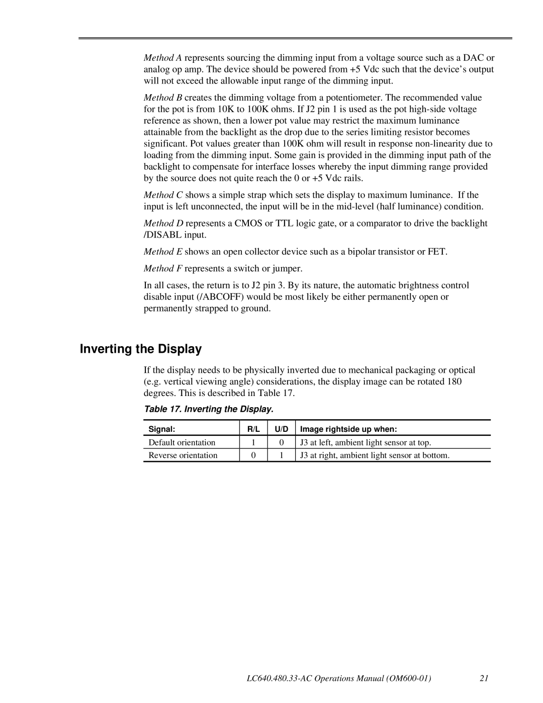
If the display needs to be physically inverted due to mechanical packaging or optical (e.g. vertical viewing angle) considerations, the display image can be rotated 180 degrees. This is described in Table 17.
Table 17. Inverting the Display.
Signal: | R/L | U/D | Image rightside up when: |
|
|
|
|
Default orientation | 1 | 0 | J3 at left, ambient light sensor at top. |
|
|
|
|
Reverse orientation | 0 | 1 | J3 at right, ambient light sensor at bottom. |
21 |