F-23371

Electronic Speed Switch Technical Manual

Page 3

Barber-Colman sets the units to operate over the

5.1.4 When an overspeed condition occurs, OS-SW2

adjustment range of 325 to 10,000 Hz by cutting

relay deenergizes and latches up and will remain

jumper J2 only. The sensitivity of the adjustment

latched up until the POWER SWITCH is turned off or

potentiometer is approximately 480 Hz per turn.

power is somehow removed from the unit. The engine

n SW1 is factory set at 1100 Hz unless specified in

overspeed setpoint is normally adjusted to trip at 10 to

purchase order.


20% above the engine operating speed.

nOS-SW2 is factory set at 3600 Hz unless specified

in purchase order.

5.2 CALIBRATION PROCEDURE

The unit can be operated at a lower frequency

Equipment Required: Signal generator

adjustment range (80 to 2500 Hz instead of 325 to

Frequency counter Ohmmeter

10,000 Hz) by reconnecting jumper J2 and cutting out


jumper J1 (see Figure 2).

5.2.1 Determine the desired trip points for your unit


when using a magnetic pickup (MPU).


4.0 WIRING INSTRUCTIONS


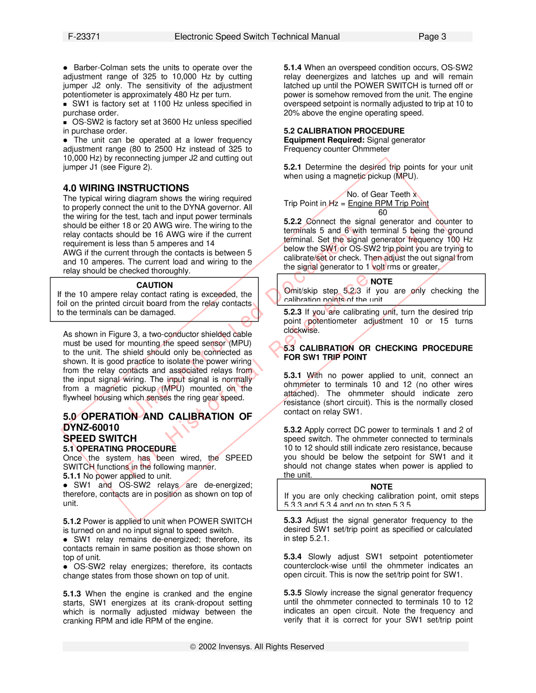
No. of Gear Teeth x


The typical wiring diagram shows the wiring required


Trip Point in Hz = Engine RPM Trip Point


to properly connect the unit to the DYNA governor. All


60


the wiring for the test, tach and input power terminals


5.2.2 Connect the signal generator and counter to


should be either 18 or 20 AWG wire. The wiring to the


Document


relay contacts should be 16 AWG wire if the current


terminals 5 and 6 wi h terminal 5 being the ground


Only


requirement is less than 5 amperes and 14


terminal. Set the signal generator frequency 100 Hz


below the SW1 or OS-SW2 trip point you are trying

to


AWG if the current through the contacts is between 5


calibrate/set or check. Then adjust the out signal from


and 10 amperes. The current load and wiring to the


the signal generator to 1 volt rms or greater.


relay should be checked thoroughly.


Reference

NOTE


shown. It is good practice to isolate he power wiring


CAUTION


Omit/skip

step

5.2.3 if

you

are only checking the

If the 10 ampere relay contact rating is exceeded, the


calibration poi ts of the unit.


foil on the printed circuit board from the relay contacts


5.2.3 If you are calibrating unit, turn the desired trip


Uncontrolled


to the terminals can be damaged.


point potentiometer adjustment 10 or 15 turns


As shown in Figure 3, a two-conductor shielded cable


clockwise.


must be used for mounting the speed sensor (MPU)


5.3 CALIBRATION OR CHECKING PROCEDURE


to the unit. The shield should only be c nnected as


FOR SW1 TRIP POINT


istorical


from the relay contacts and associa ed relays from


5.3.1 With

no

power applied to unit, connect an


the input signal wiring. The input signal is norm

lly


ohmmeter

to terminals 10 and 12 (no other wires


from a magnetic

pickup (MPU) mounted on

the


attached).

The

ohmmeter

should indicate

zero


flywheel housing which senses the ring gear speed.


resistance (short circuit). This is the normally closed


5.0 OPERATION AND CALIBRATION OF


contact on relay SW1.


DYNZ-60010


H


5.3.2 Apply correct DC power to terminals 1 and 2 of


SPEED SWITCH


speed switch. The ohmmeter connected to terminals


10 to 12 should still indicate zero resistance, because


5.1 OPERATING PROCEDURE


For


you should be below the setpoint for SW1 and it


Once the system has been wired, the SPEED


SWITCH functions in the following manner.


should not change states when power is applied to


5.1.1 No power applied to unit.


the unit.


SW1 and OS-SW2 relays are de-energized;


NOTE


therefore, contacts are in position as shown on top of


If you are only checking calibration point, omit steps


unit.


5.3.3 and 5.3.4 and go to step 5.3.5.


5.1.2 Power is applied to unit when POWER SWITCH


5.3.3 Adjust the signal generator frequency to the


is turned on and no input signal to speed switch.


desired SW1 set/trip point as specified or calculated


SW1 relay remains de-energized; therefore,

its


in step 5.2.1.


contacts remain in same position as those shown on


5.3.4 Slowly adjust SW1 setpoint potentiometer


top of unit.


OS-SW2 relay

energizes; therefore, its contacts


counterclock-wise until the ohmmeter indicates an


change states from those shown on top of unit.


open circuit. This is now the set/trip point for SW1.


5.1.3 When the engine is cranked and the engine


5.3.5 Slowly increase the signal generator frequency


starts, SW1 energizes at its crank-dropout setting


until the ohmmeter connected to terminals 10 to 12


which is normally adjusted midway between the


indicates an open circuit. Note the frequency and


cranking RPM and idle RPM of the engine.


verify that

it is

correct

for your SW1 set/trip

point

ã2002 Invensys. All Rights Reserved

Page 5
Image 5
Plantronics DYNZ-600 Series technical manual Wiring Instructions, Operation and Calibration, Speed Switch

DYNZ-600 Series specifications

The Plantronics DYNZ-600 Series represents a hallmark of innovation in the realm of professional communication headsets. Designed to meet the dynamic needs of modern workplaces, this series combines advanced technologies with user-focused features, making it ideal for both office and remote work environments.

At the heart of the DYNZ-600 Series is its exceptional audio quality, which is achieved through high-definition wideband audio. This ensures crystal-clear voice transmission, enabling users to engage in conversations without misunderstanding or the distraction of background noise. The headset also incorporates noise-canceling microphone technology, effectively filtering out ambient sounds and enhancing the clarity of voice communication. With this feature, professionals can focus on their discussions without the interference of surroundings.

Comfort is a cornerstone of the DYNZ-600 Series design. The headsets come equipped with lightweight materials and plush ear cushions, allowing users to wear them for extended periods without discomfort. The adjustable headband and flexible microphone boom further enhance the ergonomic design, ensuring a tailored fit for each user.

Another standout characteristic of the DYNZ-600 Series is its versatility in connectivity. These headsets are engineered to seamlessly connect with multiple devices, including computers, smartphones, and tablets. The inclusion of Bluetooth technology provides wireless freedom, allowing users to move around their workspace without being tethered by cables. This is particularly beneficial in busy office environments where mobility is key.

Furthermore, the DYNZ-600 Series boasts impressive battery life, offering hours of talk time on a single charge. This ensures that professionals remain connected throughout their workday without the need for frequent recharging. Additionally, a quick charge feature allows users to gain several hours of use from just a short charging session, catering to the fast-paced nature of today's work environments.

In terms of design, the DYNZ-600 Series is sleek and modern, available in various styles to suit individual preferences. With options for both over-the-ear and on-ear configurations, users can select the style that best fits their personal and professional needs.

In summary, the Plantronics DYNZ-600 Series delivers a powerful combination of superior audio quality, user-friendly features, and connectivity options that cater to the evolving requirements of today's workplaces. This series stands out as an essential tool for professionals seeking reliability, comfort, and efficiency in their communication.