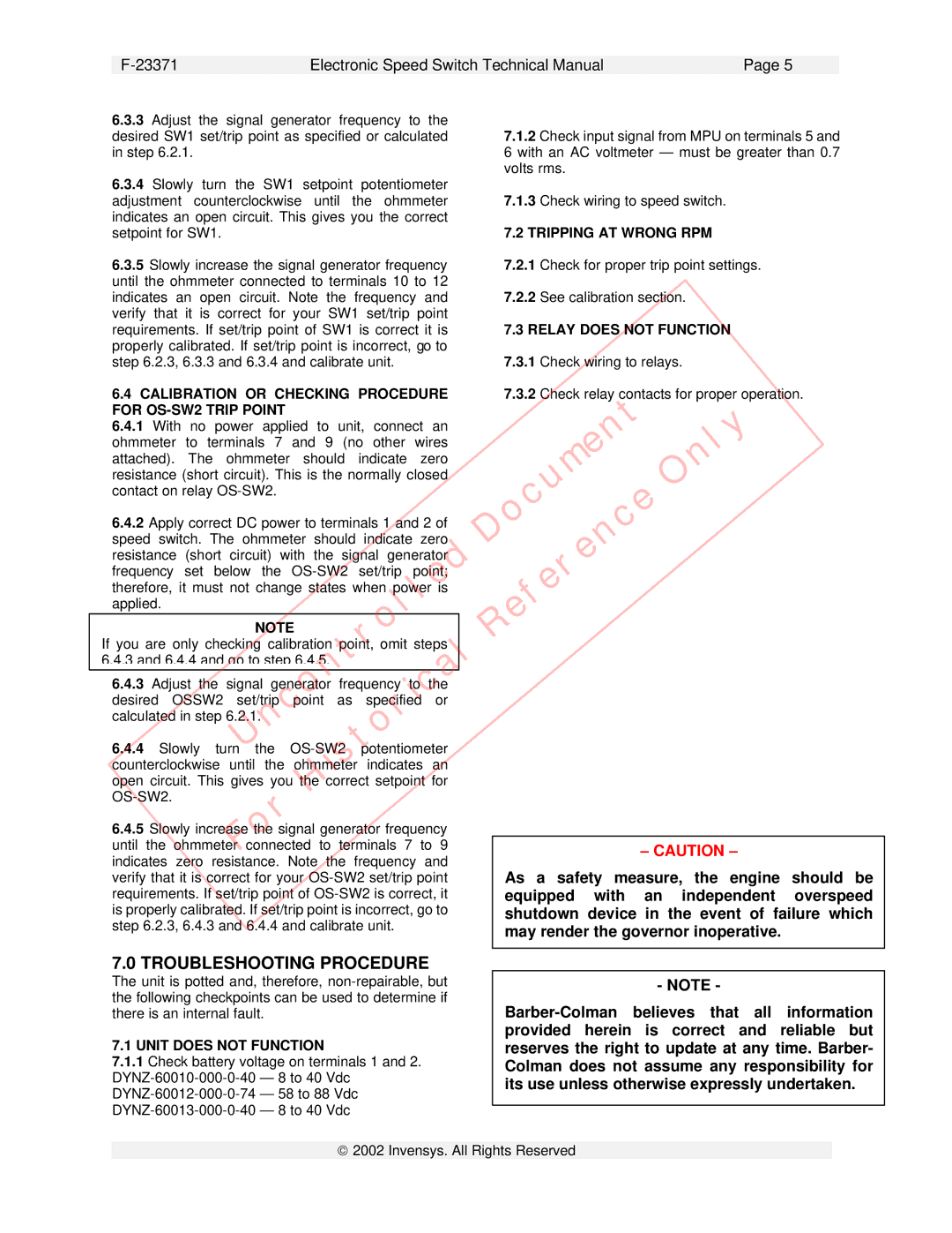
DYNZ-600 Series specifications
The Plantronics DYNZ-600 Series represents a hallmark of innovation in the realm of professional communication headsets. Designed to meet the dynamic needs of modern workplaces, this series combines advanced technologies with user-focused features, making it ideal for both office and remote work environments.At the heart of the DYNZ-600 Series is its exceptional audio quality, which is achieved through high-definition wideband audio. This ensures crystal-clear voice transmission, enabling users to engage in conversations without misunderstanding or the distraction of background noise. The headset also incorporates noise-canceling microphone technology, effectively filtering out ambient sounds and enhancing the clarity of voice communication. With this feature, professionals can focus on their discussions without the interference of surroundings.
Comfort is a cornerstone of the DYNZ-600 Series design. The headsets come equipped with lightweight materials and plush ear cushions, allowing users to wear them for extended periods without discomfort. The adjustable headband and flexible microphone boom further enhance the ergonomic design, ensuring a tailored fit for each user.
Another standout characteristic of the DYNZ-600 Series is its versatility in connectivity. These headsets are engineered to seamlessly connect with multiple devices, including computers, smartphones, and tablets. The inclusion of Bluetooth technology provides wireless freedom, allowing users to move around their workspace without being tethered by cables. This is particularly beneficial in busy office environments where mobility is key.
Furthermore, the DYNZ-600 Series boasts impressive battery life, offering hours of talk time on a single charge. This ensures that professionals remain connected throughout their workday without the need for frequent recharging. Additionally, a quick charge feature allows users to gain several hours of use from just a short charging session, catering to the fast-paced nature of today's work environments.
In terms of design, the DYNZ-600 Series is sleek and modern, available in various styles to suit individual preferences. With options for both over-the-ear and on-ear configurations, users can select the style that best fits their personal and professional needs.
In summary, the Plantronics DYNZ-600 Series delivers a powerful combination of superior audio quality, user-friendly features, and connectivity options that cater to the evolving requirements of today's workplaces. This series stands out as an essential tool for professionals seeking reliability, comfort, and efficiency in their communication.

