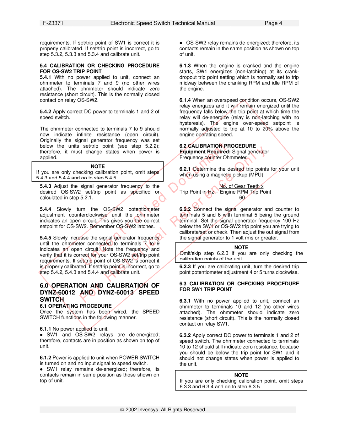
Plantronics DYNZ-600 Series Operation And Calibration Of, DYNZ-60012 AND DYNZ-60013 SPEED, Switch

Models: DYNZ-600 Series

1 7
Download 7 pages 35.01 Kb
Page 6
Image 6
5.4 CALIBRATION OR CHECKING PROCEDURE


F-23371


Electronic Speed Switch Technical Manual


Page 4


requirements. If set/trip point of SW1 is correct it is


OS-SW2 relay remains de-energized; therefore, its


properly calibrated. If set/trip point is incorrect, go to


contacts remain in the same position as shown on top


step 5.3.2, 5.3.3 and 5.3.4 and calibrate unit.


of unit.


5.4 CALIBRATION OR CHECKING PROCEDURE


6.1.3 When the engine is cranked and the engine


FOR OS-SW2 TRIP POINT


starts, SW1 energizes (non-latching) at its crank-


5.4.1 With no power applied to unit, connect an


dropout trip point setting which is normally set to trip


ohmmeter to terminals 7 and 9 (no other wires


midway between the cranking RPM and idle RPM of


attached). The ohmmeter should indicate zero


the engine.


resistance (short circuit). This is the normally closed


contact on relay OS-SW2.


6.1.4 When an overspeed

condition occurs, OS-SW2


5.4.2 Apply correct DC power to terminals 1 and 2 of


relay energizes and it will remain energized until the


frequency falls below the trip point at which time the


speed switch.


relay will de-energize (relay is non-latching with no


The ohmmeter connected to terminals 7 to 9 should


hysteresis). The engine over-speed setpoint is


normally adjusted to trip at 10 to 20% above the


now indicate infinite resistance (open circuit).


engine operating speed.


Originally


the signal generator

frequency was

set

Document


below the units set/trip point (see step 5.2.2);


6.2 CALIBRATION PROCEDURE


therefore, it must change states when power is


Equipment Required: Signal generator


applied.


Frequency counter Ohmmeter


NOTE


6.2.1 Determine the desired trip points for your unit


If

you are only checking calibration point, omit steps


when using a magnetic pickupOnly(MPU).

5.4.3 and 5.4.4 and go to step 5.4.5.


Reference


5.4.3 Adjust the signal generator frequency to the


No. of Gear Teeth x


desired OS-SW2 set/trip point as specified or


Trip Point in Hz = Engine RPM Trip Point


Uncontrolled


60


calculated in step 5.2.1.


5.4.4 Slowly turn the OS-SW2 potentiometer


6.2.2 Connect the signal generator and counter to


adjustment counterclockwise until the ohmmeter


terminals 5 and 6 with terminal 5 being the ground


indicates an open circuit. This gives you the correct


terminal. Set the signal generator frequency 100 Hz


setpoint for OS-SW2. Remember OS-SW2 latches.


below the SW1 or OS-SW2 trip point you are trying to


istorical


calibrate/set or check. Then adjust the out signal from


5.4.5 Slowly increase the signal ge

erator frequency


the signal generator to 1 volt rms or greater.


until the

ohmmeter

connected

to

terminals 7

to 9


NOTE


indicates

an open


circuit. Note

the frequency

and


Omit/skip step 6.2.3 if you are

only checking the


verify that it is correct for your OS-SW2 set/trip point


calibration points of the unit.


requirements. If set/trip point of OS-SW2 is correct it


is properly calibrated. If set/trip point is incorrect, go to


6.2.3 If you are calibrating unit, turn the desired trip


step 5.4.2, 5.4.3 and 5.4.4 and cal brate unit.


point potentiometer adjustment 4 or 5 turns clockwise.


For

H


6.3 CALIBRATION OR CHECKING PROCEDURE


6.0 OPERATION AND CALIBRATION OF


FOR SW1 TRIP POINT


DYNZ-60012 AND DYNZ-60013 SPEED


SWITCH


6.3.1 With no power applied to unit, connect an


6.1 OPERATING PROCEDURE


ohmmeter to terminals 10 and 12 (no other wires


Once the system has been wired, the SPEED


attached). The ohmmeter should indicate zero


SWITCH functions in the following manner.


resistance (short circuit). This is the normally closed


contact on relay SW1.


6.1.1No power applied to unit.

SW1 and OS-SW2 relays are de-energized;

6.3.2 Apply correct DC power to terminals 1 and 2 of

therefore, contacts are in position as shown on top of

speed switch. The ohmmeter connected to terminals

unit.

10 to 12 should still indicate zero resistance, because

6.1.2 Power is applied to unit when POWER SWITCH

you should be below the trip point for SW1 and it

should not change states when power is applied to

is turned on and no input signal to speed switch.

the unit.

SW1 relay remains de-energized; therefore, its


contacts remain in same position as those shown on

NOTE

top of unit.

If you are only checking calibration point, omit steps


6.3.3 and 6.3.4 and go to step 6.3.5.

ã2002 Invensys. All Rights Reserved

Page 6
Image 6
Plantronics DYNZ-600 Series Operation And Calibration Of, DYNZ-60012 AND DYNZ-60013 SPEED, Switch, FOR OS-SW2 TRIP POINT