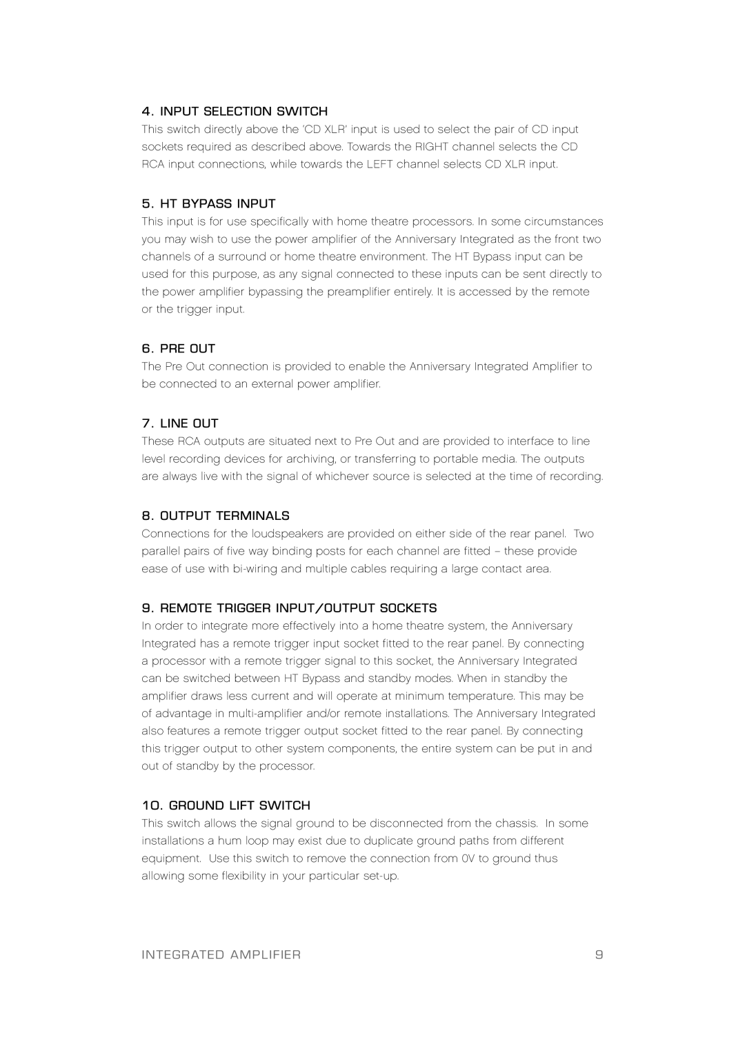
Anniversary Integrated Amplifier specifications
Plinius Audio, a renowned name in the high-fidelity audio equipment industry, has celebrated its commitment to musical excellence with the release of the Anniversary Integrated Amplifier. This exceptional amplifier blends traditional craftsmanship with cutting-edge technology, making it a potent contender for audiophiles seeking top-tier performance in a compact design.At the heart of the Anniversary Integrated Amplifier lies an impressive power output of 150 watts per channel into 8 ohms, ensuring that it can drive a variety of speaker types with authority and accuracy. The robust power supply, featuring custom-wound toroidal transformers, guarantees stable performance even during dynamic peaks. The amplifier is built around a fully balanced design, which minimizes noise and distortion while enhancing the clarity of the audio signal.
One of the standout features of the Anniversary Integrated Amplifier is its innovative circuit topology. Plinius has employed a combination of Class A and Class AB designs to achieve a perfect balance between warmth and efficiency. This hybrid approach allows the amplifier to deliver rich, detailed sound without compromising on energy efficiency. The use of proprietary technology, such as the Plinius Active Feedback system, further refines the audio output, providing an immersive listening experience and exceptional dynamic range.
Additional features of the Anniversary Integrated Amplifier include an integrated digital-to-analog converter (DAC) that supports high-resolution audio formats. This built-in DAC enhances versatility, enabling users to connect their digital sources seamlessly, from streaming services to high-end digital players. For those who appreciate analog sources, the amplifier also includes a high-quality phono stage, catering to vinyl enthusiasts who cherish the warmth and texture of analog sound.
The design of the Anniversary Integrated Amplifier reflects Plinius’ dedication to aesthetics and functionality. Its elegant aluminum chassis is both durable and visually appealing, complete with a user-friendly interface that allows for easy operation. The amplifier features multiple analog and digital inputs, making it flexible enough to accommodate various audio components.
In summary, the Plinius Audio Anniversary Integrated Amplifier exemplifies the brand's commitment to quality and innovation. With its powerful output, balanced circuit design, and thoughtful integration of modern technology, this amplifier not only delivers superb sound quality but also ensures that it remains a centerpiece in any high-fidelity audio setup. For those seeking a blend of sophistication and performance, the Anniversary Integrated Amplifier stands out as an exceptional choice.

