1

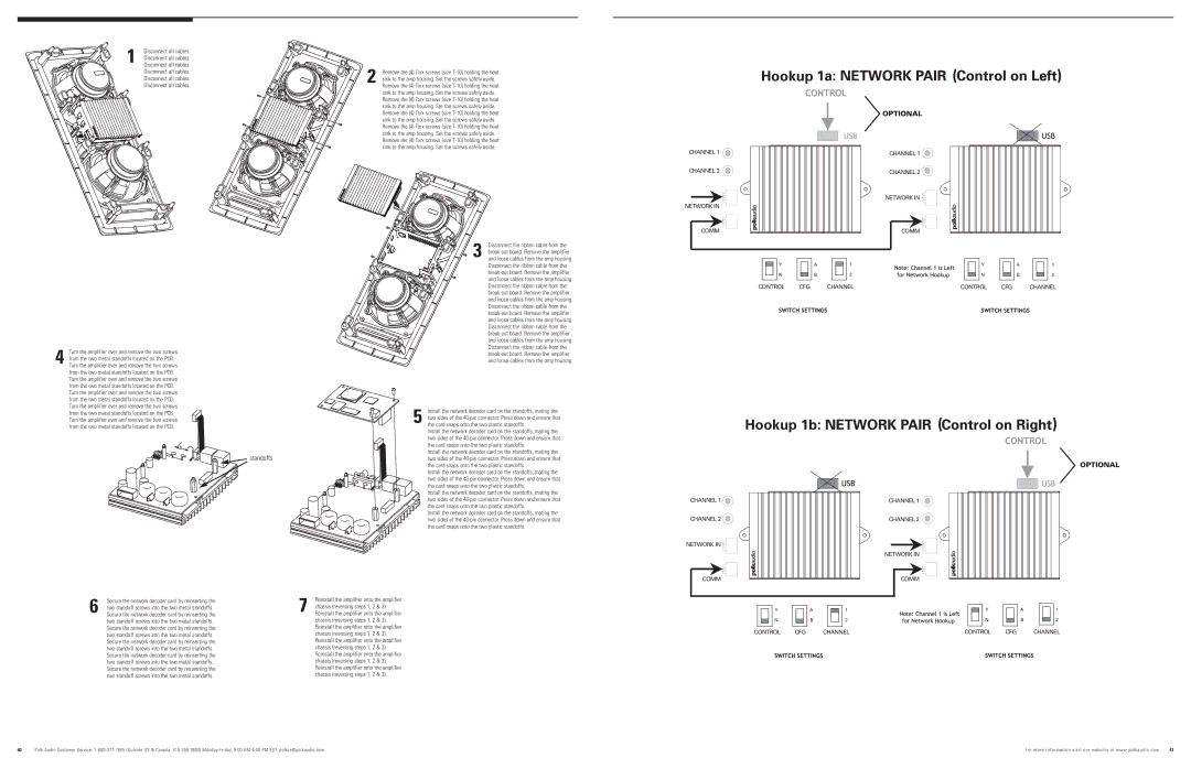
Disconnect all cables.

Disconnect all cables.

Disconnect all cables.

Disconnect all cables.

Disconnect all cables.

Disconnect all cables.

2 Remove the (4) Torx screws (size T-10) holding the heat sink to the amp housing. Set the screws safely aside. Remove the (4) Torx screws (size T-10) holding the heat sink to the amp housing. Set the screws safely aside. Remove the (4) Torx screws (size T-10) holding the heat sink to the amp housing. Set the screws safely aside. Remove the (4) Torx screws (size T-10) holding the heat sink to the amp housing. Set the screws safely aside. Remove the (4) Torx screws (size T-10) holding the heat sink to the amp housing. Set the screws safely aside. Remove the (4) Torx screws (size T-10) holding the heat sink to the amp housing. Set the screws safely aside.

Hookup

OPTIONAL

CHANNEL 1

CHANNEL 2

NETWORK IN

COMM

CHANNEL 1

CHANNEL 2

NETWORK IN

COMM

4

Turn the amplifier over and remove the two screws

from the two metal standoffs located on the PCB.

Turn the amplifier over and remove the two screws

Disconnect the ribbon cable from the

3 break-out board. Remove the amplifier and loose cables from the amp housing. Disconnect the ribbon cable from the break-out board. Remove the amplifier and loose cables from the amp housing. Disconnect the ribbon cable from the break-out board. Remove the amplifier and loose cables from the amp housing. Disconnect the ribbon cable from the break-out board. Remove the amplifier and loose cables from the amp housing. Disconnect the ribbon cable from the break-out board. Remove the amplifier and loose cables from the amp housing. Disconnect the ribbon cable from the break-out board. Remove the amplifier and loose cables from the amp housing.

YA1

N


B

2


CONTROL CFG CHANNEL

YA1

NB2

CONTROL CFG CHANNEL

from the two metal standoffs located on the PCB. Turn the amplifier over and remove the two screws from the two metal standoffs located on the PCB. Turn the amplifier over and remove the two screws from the two metal standoffs located on the PCB. Turn the amplifier over and remove the two screws from the two metal standoffs located on the PCB. Turn the amplifier over and remove the two screws from the two metal standoffs located on the PCB.


Install the network decoder card on the standoffs, mating the


two sides of the 40-pin connector. Press down and ensure that


5 the card snaps onto the two plastic standoffs.


Install the network decoder card on the standoffs, mating the


two sides of the 40-pin connector. Press down and ensure that


the card snaps onto the two plastic standoffs.

standoffs

Install the network decoder card on the standoffs, mating the

two sides of the 40-pin connector. Press down and ensure that


the card snaps onto the two plastic standoffs.


Install the network decoder card on the standoffs, mating the


two sides of the 40-pin connector. Press down and ensure that


the card snaps onto the two plastic standoffs.


Install the network decoder card on the standoffs, mating the


two sides of the 40-pin connector. Press down and ensure that


the card snaps onto the two plastic standoffs.


Install the network decoder card on the standoffs, mating the


two sides of the 40-pin connector. Press down and ensure that


the card snaps onto the two plastic standoffs.

Hookup

CHANNEL 1

CHANNEL 2

NETWORK IN

COMM

OPTIONAL

CHANNEL 1

CHANNEL 2

NETWORK IN

COMM

6

Secure the network decoder card by reinserting the

two standoff screws into the two metal standoffs.

Secure the network decoder card by reinserting the

two standoff screws into the two metal standoffs. Secure the network decoder card by reinserting the two standoff screws into the two metal standoffs. Secure the network decoder card by reinserting the two standoff screws into the two metal standoffs. Secure the network decoder card by reinserting the two standoff screws into the two metal standoffs. Secure the network decoder card by reinserting the two standoff screws into the two metal standoffs.

Reinstall the amplifier onto the amplifier

7 chassis (reversing steps 1, 2 & 3). Reinstall the amplifier onto the amplifier chassis (reversing steps 1, 2 & 3). Reinstall the amplifier onto the amplifier chassis (reversing steps 1, 2 & 3). Reinstall the amplifier onto the amplifier chassis (reversing steps 1, 2 & 3). Reinstall the amplifier onto the amplifier chassis (reversing steps 1, 2 & 3). Reinstall the amplifier onto the amplifier chassis (reversing steps 1, 2 & 3).

YA1

NB2

CONTROL CFG CHANNEL

YA1

NB2

CONTROL CFG CHANNEL

40Polk Audio Customer Service: 1-800-377-7655 (Outside US & Canada: 410-358-3600) Monday-Friday, 9:00 AM-6:00 PM EST, polkcs@polkaudio.com

For more information visit our website at www.polkaudio. com

41

Page 6
Image 6
Polk Audio LC80i-IP, LC265i-IP owner manual Hookup

LC265i-IP, LC80i-IP specifications

Polk Audio has long been recognized for its commitment to delivering high-quality audio experiences, and the LC265i-IP and LC80i-IP speakers are no exception. These in-ceiling speakers are designed to provide immersive sound while seamlessly blending into any home environment and are particularly suitable for music enthusiasts and home theater aficionados alike.

The LC265i-IP is a component of Polk's Architectural Series, featuring a 6.5-inch Dynamic Balance woofer that ensures deep bass and clear midrange frequencies. It is complemented by a 1-inch silk dome tweeter that delivers sweet highs and provides a balanced audio profile. The speakers are engineered with Polk's innovative PowerPort technology, which enhances low-frequency output without distortion, resulting in a richer sound experience. This design not only improves audio performance but also reduces air turbulence, making for a cleaner and more enjoyable listening experience.

The LC80i-IP, on the other hand, features an 8-inch Dynamic Balance woofer and a 1-inch silk dome tweeter, capable of delivering robust sound in larger spaces. The increased woofer size allows for deeper bass response and greater sound dispersion, making it ideal for larger rooms or home theater setups. Both speakers incorporate a 15-degree angled design that allows for targeted sound placement, ensuring that every listener experiences optimal sound quality, regardless of their position in the room.

Both the LC265i-IP and LC80i-IP speakers utilize Polk's patented Moisture Resistant technology, making them compatible for use in high-humidity areas such as kitchens, bathrooms, or exterior locations. Their innovative design allows for easy installation in ceiling cavities and walls, with a low-profile appearance that maintains the aesthetic of any space.

In terms of construction, these speakers feature a durable but lightweight design, enhancing long-term performance without compromising sound quality. The paintable grill allows customization to match your home decor perfectly, ensuring that the speakers blend seamlessly with your interior.

Overall, the Polk Audio LC265i-IP and LC80i-IP speakers offer a beautiful combination of advanced technology, versatility, and aesthetics, making them an excellent choice for anyone looking to enhance their audio experience. Whether you are setting up a dedicated home theater or simply enjoying music in your living space, these speakers are designed to deliver exceptional sound quality that you can enjoy for years to come.