INSTALLING LCi-IP SPEAKERS
INSTALLATION RECOMMENDATION FOR OPTIMUM PERFORMANCE
Note: Polk Audio performance enclosures are sold separately.
Polk Audio Performance Enclosures offer the best possible sound quality with pre-construction and major renovation installations. They are perfect volume cabi- nets that provide LCi-IP speakers with the ideal volume and internal damping material for optimum bass per- formance. They are constructed of rigid MDF and exten- sively braced to ensure that all of the speaker's energy works to produce tight, clean, low distortion bass. Polk provides brackets, gaskets and all the hardware you need to do a quick and rattle-free installation. LCi-IP Performance Enclosures guarantee the most consistent, dynamic, full-spectrum sound with superior bass exten- sion. As an added bonus, homeowners will enjoy superior room-to-room sound isolation.
OTHER OPTIONS
Better Sound
When you can't install a Performance Enclosure but want to get better bass, install fire breaks above and below the speaker position to make an ideal-volume enclosure. Also, a layer of fiberglass or Dacron® behind the speaker helps.
Note: Leave space around the speaker’s amplifier; insulating material must not come in contact with the amplifier.
Important Note: If installing LCi-IP speakers in an external wall, the operating ambient temperature of the speakers is 0-50° C (32-122° F). For most types of construction, the external walls will be insulated, but it
is important that insulation does not come in con- tact with the speaker’s amplifier.
Pre-construction Brackets are available to locate the speaker and tie off wires before the drywall installers finish their work. Order the LCi-IP Pre-Construction Brackets by contacting Polk Audio's Sales Department at 800-638-7276.
Good Sound
Cut a hole for the speaker, feed the wires, and simply drop the speaker in. Polk Audio's unique, rotating cams secure the speaker safely with no extra assembly or mess. LCi-IP Loudspeakers are designed to outperform any other custom install speaker, even when they're simply dropped into the wall or ceiling.
WIRE RECOMMENDATIONS
Network Line
Shielded Cat-5 cable with RJ-45 connectors. Wiring termination convention should be the same at both ends of the cable.
COMM Line
Shielded Cat-5 cable with RJ-45 connectors. Wiring termination convention should be the same at both ends of the cable.
Analog Line
Low capacitance multi-stranded RCA shielded cable.
Cable runs up to 100 feet should have a capacitance of 20pF/ft. For cable runs greater than 100 ft. call Customer Serivce at 1-800-377-7655.
USB Connection
USB 1.1, 5-wire, USB to mini-USB cable.
Power Lines
These recommendations are for all connections from the power supply to each speaker:
| | Wire gauge/ | Wire Length |
| | # of Conductors | | |
Optimal | 14/4 | 1’ |
| | | | |
| | | | | |
Acceptable | 16/2 | 150’ |
Cable Installation Tips
•Observe the proper polarity at each connector.
•Wall insulation should never come in contact with the amplifier located on the back of each speaker.
•Never kink or bend any cable, nor should any cable interfere with other cables.
•Never try to make a short cable reach, ever.
•Avoid long cable runs if possible — the shorter the cable, the better the sound quality. Do, however, ensure that your cables are long enough.
•Cable should be at least 3 feet away from fluorescent light boxes and other sources of electrical interference.
•Label both ends of each cable.
•Always keep AC power cords and analog
power cords separate.
INSTALLING THE NETWORK DECODER CARD
Introduction
You will need to install a netword decoder card to use the “network.” Follow the directions below to install the card. There is also a series of schematic diagrams (on page 38) to help you properly connect the speakers to a network or analog system.
Note: A network decoder card is not needed to use the analog RCAs.
Step 1: Disconnect all cables.
Step 2: Remove the (4) screws holding the heat sink to the amplifier housing. Set the screws safely aside.
Step 3: Remove the amplifier and loose cables from the amplifier housing.
Step 4: Remove the two screws from the two metal standoffs located on the PCB.
Step 5: Install the network decoder card on the standoffs, mating the two sides of the
40-pin connector. Press down and ensure that the card snaps onto the two plastic standoffs.
Step 6: Secure the network decoder card by reinserting the two standoff screws into the two metal standoffs.
Step 7: Reinstall the amplifier onto the amplifier chassis (reversing steps 1, 2 & 3).
CONNECTING LCi-IP SPEAKERS TO A NETWORK OR ANALOG SYSTEM
This is the list of speaker connection options, which are shown schematically on pages 39-43:
1a. Network pair (Control on Left)
1b. Network pair (Control on Right)
2.Network (Independent Control)
3a. Analog pair (Control on Left)
3b. Analog pair (Control on Right)
4a. Analog pair (Control on Left)
4b. Analog pair (Control on Right)
When using a Center Channel with an analog pair
5a. Analog (Independent control when used with either Hookup 3a or 3b)
5b. Analog (Independent control when used with either Hookup 4a or 4b)
Important Note: Switch settings are located on the back of the speaker baffle.
Reset Button Reminder
Note: Each speaker has a RESET BUTTON, which is accessible through a clearly-marked hole on the front of the speaker.
Engage the RESET BUTTON whenever you:
• Reconfigure the switch settings. |
• Update the firmware on the network decoder card. |
• Update the amplifier’s firmware. |
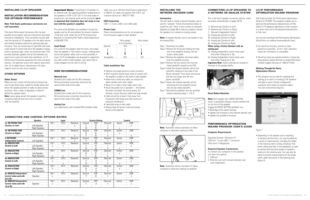
LCi-IP PERFORMANCE OPTIMIZATION WIZARD PROGRAM
Polk Audio provides the Performance Optimization Wizard on CD-ROM. This program enables you to optimize the performance characteristics of Polk Audio LCi-IP speakers specifically to their location in a given room and to the physical characteristics of that room.
You can also download the Performance Optimization Wizard from our website (www.polkaudio.com).
•For maximum accuracy, answer as many questions as possible. Do not ”skip” questions unless the information is unavailable.
•Should you have any questions before or during the setup process, please feel free to contact Polk Audio Installer Support Services at 1-800-377-POLK.
Walking Through the Room
Optimization Choices
•This program can be used for installing and setting up in-wall or in-ceiling LCi-IP speakers and asks a series of basic configuration questions and a series of questions about the room environment (figure1).
CONNECTION AND CONTROL OPTIONS MATRIX
| Speaker | | Input | | | Switch Setting | | | Control |
1a: NETWORK PAIR | | CH 1 | CH 2 | Network | Control | | CFG | | Channel | Comm | USB |
(Control on Left) | Left Speaker | | | x | Y | | B | | 1 | | x |
| Right Speaker | | | | N | | B | | 2 | x | |
1b: NETWORK PAIR | | CH 1 | CH 2 | Network | Control | | CFG | | Channel | Comm | USB |
(Control on Right) | Left Speaker | | | | N | | B | | 1 | x | |
| Right Speaker | | | x | Y | | B | | 2 | | x |
2: NETWORK | | CH 1 | CH 2 | Network | Control | | CFG | | Channel | Comm | USB |
(Independent Control) | Left Speaker | | | x | Y | | B | | 1 | | x |
3a: ANALOG PAIR | | CH 1 | CH 2 | Network | Control | | CFG | | Channel | Comm | USB |
(Control on Left) | Left Speaker | x | x | | Y | | B | | 1 | | x |
| Right Speaker | | | | N | | B | | 2 | x | |
3b: ANALOG PAIR | | CH 1 | CH 2 | Network | Control | | CFG | | Channel | Comm | USB |
(Control on Right) | Left Speaker | | | | N | | B | | 1 | x | |
| Right Speaker | x | x | | Y | | B | | 2 | | x |
4a: ANALOG PAIR | | CH 1 | CH 2 | Network | Control | | CFG | | Channel | Comm | USB |
(Control on Left) | Left Speaker | x | | | Y | | A | | 1 | | x |
| Right Speaker | | x | | N | | A | | 2 | x | |
4b: ANALOG PAIR | | CH 1 | CH 2 | Network | Control | | CFG | | Channel | Comm | USB |
(Control on Right) | Left Speaker | x | | | N | | A | | 1 | x | |
| Right Speaker | | x | | Y | | A | | 2 | | x |
5a: ANALOG (Independent | | CH 1 | CH 2 | Network | Control | | CFG | | Channel | Comm | USB |
Control when used with | Speaker | x | | | Y | | B | | 1 | | x |
3a or 3b) | | | | | | | | | | | |
5b: ANALOG (Independent | | CH 1 | CH 2 | Network | Control | | CFG | | Channel | Comm | USB |
Control when used with | Speaker | x | | | Y | | A | | 1 | | x |
4a or 4b) | | | | | | | | | | | |
Note: Illustration shows orientation of ribbon connector to silkscreen marking on PCB.
Note: Illustration shows orientation of ribbon connector to silkscreen marking on amplifier.
PERFORMANCE OPTIMIZATION WIZARD PROGRAM USER’S GUIDE
Computer Requirements
Operating System: Windows XP
USB Port : 5-wire USB 1.1 connector
Hard drive: 5 Megabytes
Required Speaker Connections
To connect your computer to the speaker, you have two options:
1.USB port
2.Ethernet jack with network decoder card (sold separately).
Figure 1
• Depending on the speaker you’re installing, its location and the room, you may be asked for a series of measurements, including the height of the listening room's ceiling, distances from walls, ceiling and floor to the speaker(s), as well as vertical and horizontal angles of speakers relative to the listening area. You may also be asked to provide measurements for the height, width, depth and center of the listening area (figure 2).