A
B
Fig. 2
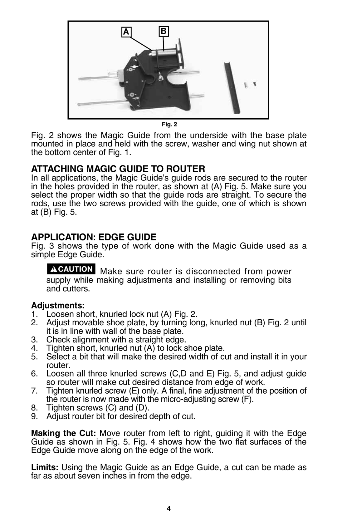
Fig. 2 shows the Magic Guide from the underside with the base plate mounted in place and held with the screw, washer and wing nut shown at the bottom center of Fig. 1.
ATTACHING MAGIC GUIDE TO ROUTER
In all applications, the Magic Guide’s guide rods are secured to the router in the holes provided in the router, as shown at (A) Fig. 5. Make sure you select the proper width so that the guide rods are straight. To secure the rods, use the two screws provided with the guide, one of which is shown at (B) Fig. 5.
APPLICATION: EDGE GUIDE
Fig. 3 shows the type of work done with the Magic Guide used as a simple Edge Guide.
 Make sure router is disconnected from power supply while making adjustments and installing or removing bits and cutters.
Adjustments:
1.Loosen short, knurled lock nut (A) Fig. 2.
2.Adjust movable shoe plate, by turning long, knurled nut (B) Fig. 2 until it is in line with wall of the base plate.
3.Check alignment with a straight edge.
4.Tighten short, knurled nut (A) to lock shoe plate.
5.Select a bit that will make the desired width of cut and install it in your router.
6.Loosen all three knurled screws (C,D and E) Fig. 5, and adjust guide so router will make cut desired distance from edge of work.
7.Tighten knurled screw (E) only. A final, fine adjustment of the position of the router is now made with the
8.Tighten screws (C) and (D).
9.Adjust router bit for desired depth of cut.
Making the Cut: Move router from left to right, guiding it with the Edge Guide as shown in Fig. 5. Fig. 4 shows how the two flat surfaces of the Edge Guide move along on the edge of the work.
Limits: Using the Magic Guide as an Edge Guide, a cut can be made as far as about seven inches in from the edge.
4
