7312, 7319, 7320, 7310 specifications
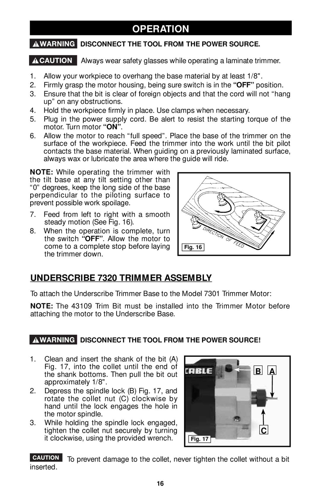
The Porter-Cable 7310 is a highly versatile and reliable product in the realm of power tools, particularly known for its efficient and reliable design. As a rotary sander, it stands out in both professional and DIY circles, offering a blend of power, convenience, and user-friendly features which make it a staple in woodworking, furniture refinishing, and other sanding applications.One of the main features of the Porter-Cable 7310 is its powerful motor, which delivers a significant amount of orbital action—up to 22,000 OPM (orbits per minute). This capability ensures that users can achieve a smooth finish in a variety of materials, from wood to plastics, without the risk of damaging the surface. The motor’s power combined with the random orbit design minimizes swirl marks while enhancing the overall finish quality, making it ideal for detailed work.
The design of the Porter-Cable 7310 is another highlight. It incorporates an ergonomic grip that reduces user fatigue during extended periods of use. The lightweight yet sturdy construction allows for easy maneuverability, enabling users to sand both flat and contoured surfaces with ease. Additionally, the integrated dust bag is a feature that aligns with modern workshop practices, helping to keep the work area clean and minimizing health risks associated with airborne dust particles.
Another technological innovation in the Porter-Cable 7310 is its hook-and-loop sanding pad attachment system. This design simplifies the process of changing sanding discs, saving valuable time during projects. The orbital sander is compatible with a wide range of sanding discs, including options with varying grits, making it adaptable to different tasks, from heavy stock removal to ultra-fine finishing.
Moreover, the Porter-Cable 7310 is built with durability in mind. Its robust construction is meant to withstand the rigors of daily use in both commercial and home environments. Users have praised its ability to operate quietly, contributing to a more pleasant working atmosphere.
In conclusion, the Porter-Cable 7310 is a powerful and efficient rotary sander, combining exceptional performance features with ease of use. Its lightweight design, effective dust collection system, and user-friendly sanding disc attachment make it a preferred choice for both professionals and hobbyists alike. Whether tackling large projects or intricate detailing, the Porter-Cable 7310 delivers consistent results, proving itself as an indispensable tool for sanding tasks.

