902388 -
A
➡
➡
➡
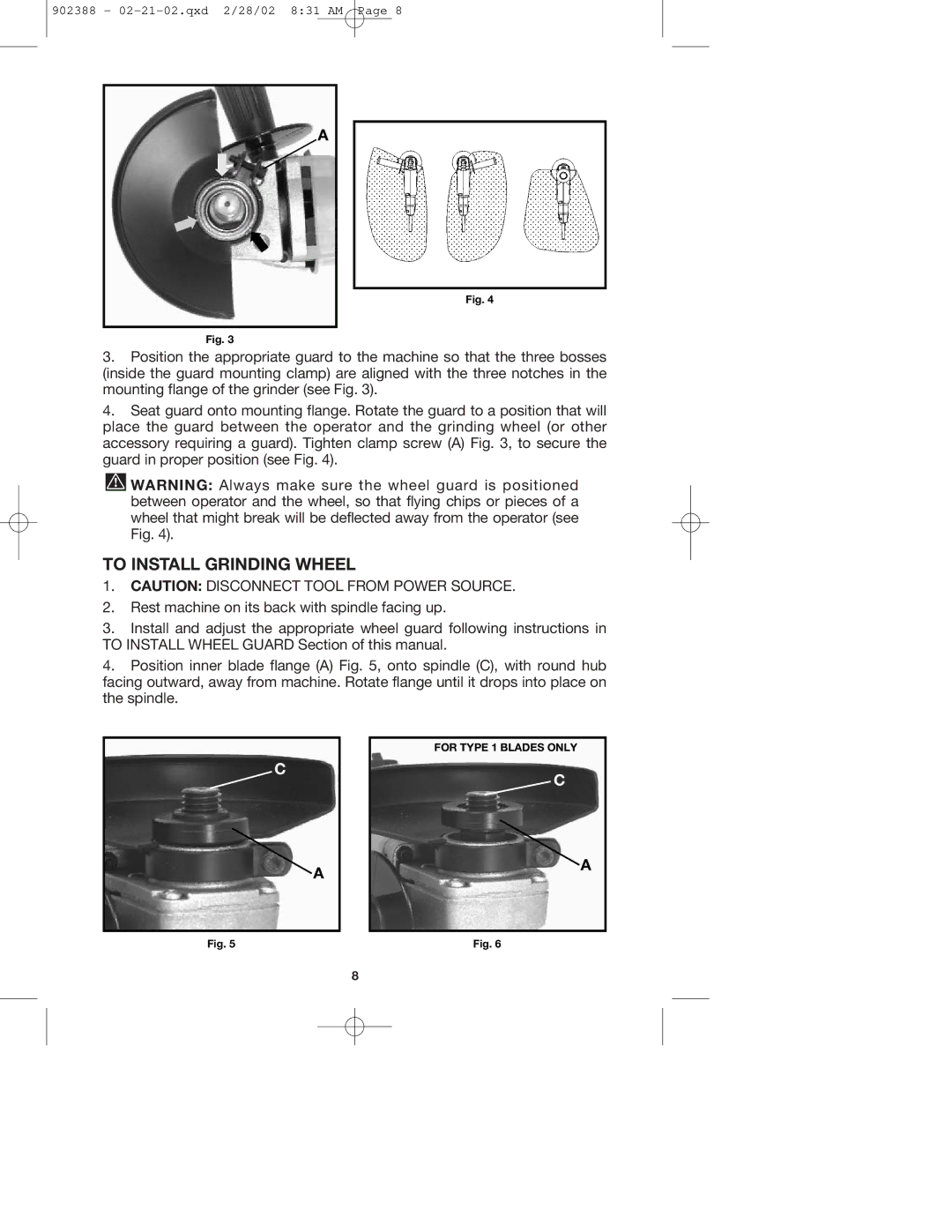
Fig. 3
Fig. 4
3.Position the appropriate guard to the machine so that the three bosses (inside the guard mounting clamp) are aligned with the three notches in the mounting flange of the grinder (see Fig. 3).
4.Seat guard onto mounting flange. Rotate the guard to a position that will place the guard between the operator and the grinding wheel (or other accessory requiring a guard). Tighten clamp screw (A) Fig. 3, to secure the guard in proper position (see Fig. 4).
![]() WARNING: Always make sure the wheel guard is positioned between operator and the wheel, so that flying chips or pieces of a wheel that might break will be deflected away from the operator (see Fig. 4).
WARNING: Always make sure the wheel guard is positioned between operator and the wheel, so that flying chips or pieces of a wheel that might break will be deflected away from the operator (see Fig. 4).
TO INSTALL GRINDING WHEEL
1.CAUTION: DISCONNECT TOOL FROM POWER SOURCE.
2.Rest machine on its back with spindle facing up.
3.Install and adjust the appropriate wheel guard following instructions in TO INSTALL WHEEL GUARD Section of this manual.
4.Position inner blade flange (A) Fig. 5, onto spindle (C), with round hub facing outward, away from machine. Rotate flange until it drops into place on the spindle.
C
FOR TYPE 1 BLADES ONLY
C
A
A
Fig. 5 | Fig. 6 |
8