FUNCTIONAL DESCRIPTION
FOREWORD
ASSEMBLY
NOTE: This tool is shipped completely assembled. Assembly time to install HANDLE, WHEEL GUARD and GRINDING WHEEL is required and should take 15 minutes or less. A 4mm hex wrench (supplied) is required to install the WHEEL GUARD. The HANDLE serves as an wrench to install the GRINDING WHEEL.
TO INSTALL AUXILIARY HANDLE
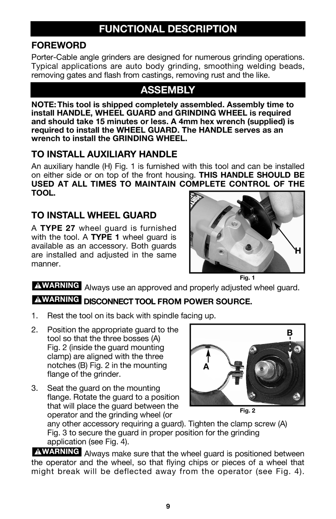
An auxiliary handle (H) Fig. 1 is furnished with this tool and can be installed on either side or on top of the front housing. THIS HANDLE SHOULD BE
USED AT ALL TIMES TO MAINTAIN COMPLETE CONTROL OF THE TOOL.
TO INSTALL WHEEL GUARD |
| |
A TYPE 27 wheel guard is furnished |
| |
with the tool. A TYPE 1 wheel guard is |
| |
available as an accessory. Both guards | H | |
are installed and adjusted in the same | ||
| ||
manner. |
| |
|
| |
| Fig. 1 |
![]() Always use an approved and properly adjusted wheel guard.
Always use an approved and properly adjusted wheel guard.
 DISCONNECT TOOL FROM POWER SOURCE.
1.Rest the tool on its back with spindle facing up.
2. Position the appropriate guard to the | B | ||
tool so that the three bosses (A) | |||
|
| ||
|
| ||
Fig. 2 (inside the guard mounting |
|
| |
|
| ||
clamp) are aligned with the three |
|
| |
notches (B) Fig. 2 in the mounting | A | ||
flange of the grinder. |
|
| |
3.Seat the guard on the mounting flange. Rotate the guard to a position that will place the guard between the
operator and the grinding wheel (or
any other accessory requiring a guard). Tighten the clamp screw (A) Fig. 3 to secure the guard in proper position for the grinding application (see Fig. 4).
![]() Always make sure that the wheel guard is positioned between the operator and the wheel, so that flying chips or pieces of a wheel that might break will be deflected away from the operator (see Fig. 4).
Always make sure that the wheel guard is positioned between the operator and the wheel, so that flying chips or pieces of a wheel that might break will be deflected away from the operator (see Fig. 4).
9