901891 - 08-31-01.qxd 2/13/02 11:52 AM Page 11
WARNING: Disconnect tool from air supply and/or remove battery before performing maintenance, clearing a jammed fastener, leaving work area, moving tool to another location, handing the tool to another person, making adjustments.
WARNING: Clean and inspect tool daily. Carefully check for proper operation of trigger and safety mechanism. Do Not use the tool unless both the trigger and the safety mechanism are functional, or if the tool is leaking air or needs any other repair.
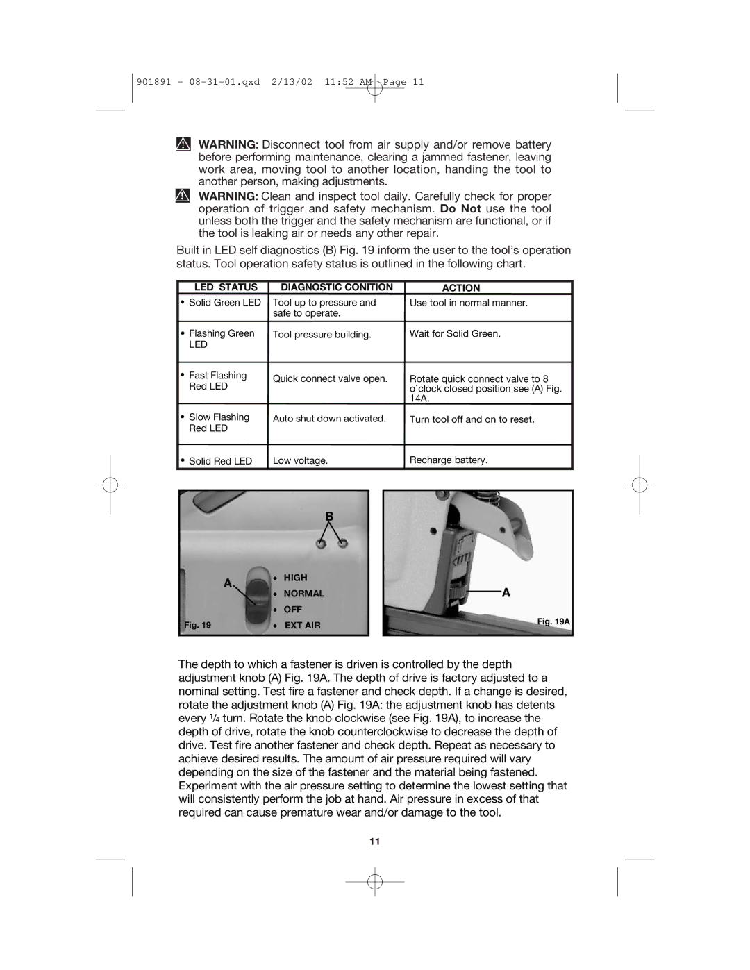
Built in LED self diagnostics (B) Fig. 19 inform the user to the tool’s operation status. Tool operation safety status is outlined in the following chart.
LED STATUS | DIAGNOSTIC CONITION | ACTION |
• Solid Green LED | Tool up to pressure and | Use tool in normal manner. |
| safe to operate. |
|
|
|
|
• Flashing Green | Tool pressure building. | Wait for Solid Green. |
LED |
|
|
• | Fast Flashing | Quick connect valve open. |
| Red LED | |
|
| |
• | Slow Flashing | Auto shut down activated. |
| Red LED |
|
Rotate quick connect valve to 8 o’clock closed position see (A) Fig. 14A.
Turn tool off and on to reset.
• Solid Red LED | Low voltage. | Recharge battery. |
B
| A | • | HIGH |
|
| NORMAL | |
|
| • | |
|
| • | OFF |
Fig. 19 |
| • | EXT AIR |
A
Fig. 19A
The depth to which a fastener is driven is controlled by the depth adjustment knob (A) Fig. 19A. The depth of drive is factory adjusted to a nominal setting. Test fire a fastener and check depth. If a change is desired, rotate the adjustment knob (A) Fig. 19A: the adjustment knob has detents every 1/4 turn. Rotate the knob clockwise (see Fig. 19A), to increase the depth of drive, rotate the knob counterclockwise to decrease the depth of drive. Test fire another fastener and check depth. Repeat as necessary to achieve desired results. The amount of air pressure required will vary depending on the size of the fastener and the material being fastened. Experiment with the air pressure setting to determine the lowest setting that will consistently perform the job at hand. Air pressure in excess of that required can cause premature wear and/or damage to the tool.
11