WARNING: Always stop unit and dis- connect spark plug before removing or instal- ling attachments.

REMOVING TRIMMER ATTACH- MENT (OR OTHER OPTIONAL ATTACHMENTS)

CAUTION: When removing or installing at- tachments, place the unit on a flat surface for stability.

1.Loosen the coupler by turning the knob counterclockwise.

Coupler

AttachmentLOOSEN

Knob

TIGHTEN

2. Press and hold the locking/release button.

Locking/Release

Button

Attachment

Coupler

Upper Shaft

3.While securely holding the engine and upper shaft, pull the attachment straight out of the coupler.

INSTALLING OPTIONAL ATTACH- MENTS

1.Remove the shaft cap from the attach- ment (if present).

2.Position locking/release button of attach- ment into guide recess of coupler.

3.Push the attachment into the coupler until the locking/release button snaps into the primary hole.

4.Before using the unit, tighten the knob se- curely by turning clockwise.

Coupler Primary Hole

Guide Recess

Locking/

Upper Release Attachment

Shaft Button

WARNING: Make sure the locking/ release button is locked in the primary hole and the knob is securely tightened before op- erating the unit. All attachments are designed to be used in the primary hole unless otherwise stated in the applicable attachment instruction manual. Using the wrong hole could lead to seri- ous injury or damage to the unit.

Locking/Release

Button in Primary Hole

OPERATING INSTRUCTIONS

It is recommended that the engine not be operated for longer than 1 minute at full throttle.

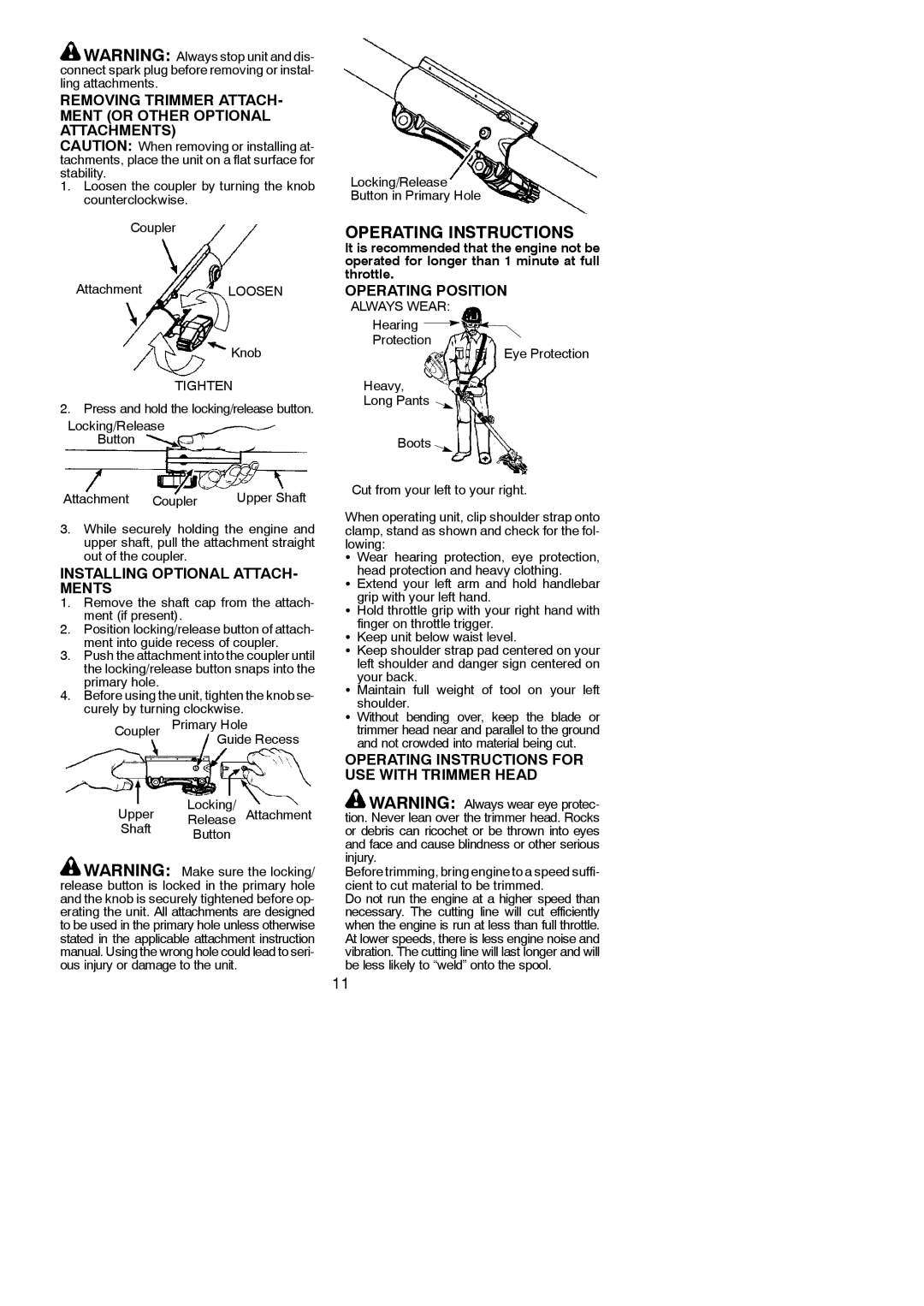
OPERATING POSITION

ALWAYS WEAR:

Hearing

Protection

Eye Protection

Heavy,

Long Pants

Boots

Cut from your left to your right.

When operating unit, clip shoulder strap onto clamp, stand as shown and check for the fol- lowing:

S Wear hearing protection, eye protection, head protection and heavy clothing.

S Extend your left arm and hold handlebar grip with your left hand.

SHold throttle grip with your right hand with

finger on throttle trigger.

SKeep unit below waist level.

SKeep shoulder strap pad centered on your

left shoulder and danger sign centered on your back.

S Maintain full weight of tool on your left shoulder.

S Without bending over, keep the blade or trimmer head near and parallel to the ground and not crowded into material being cut.

OPERATING INSTRUCTIONS FOR USE WITH TRIMMER HEAD

WARNING: Always wear eye protec- tion. Never lean over the trimmer head. Rocks or debris can ricochet or be thrown into eyes and face and cause blindness or other serious injury.

Before trimming, bring engine to a speed suffi- cient to cut material to be trimmed.

Do not run the engine at a higher speed than necessary. The cutting line will cut efficiently when the engine is run at less than full throttle. At lower speeds, there is less engine noise and vibration. The cutting line will last longer and will be less likely to “weld” onto the spool.

11

Page 11
Image 11
Poulan 952711880, 115274026 Removing Trimmer ATTACH- Ment or Other Optional Attachments, Installing Optional ATTACH- Ments

952711880, 115274026 specifications

The Poulan 952711880 and 115274026 are essential components in the world of outdoor power equipment, specifically designed to enhance the performance of various Poulan chainsaws. These two model numbers pertain to vital accessories that contribute to the functionality and efficiency of chainsaws, ensuring that they operate smoothly and effectively in a range of cutting applications.

The Poulan 952711880 is primarily a replacement chain, known for its durable design and reliable performance. This chain features a unique cutting tooth design that allows for efficient wood cutting, making it ideal for both professional and hobbyist lumberjacks. The 952711880 is designed to provide optimal cutting efficiency, reducing the effort needed to fell trees, prune limbs, or cut firewood. Its high carbon steel construction not only enhances durability but also ensures that the chain maintains its sharpness over extended periods, minimizing the need for frequent sharpening.

On the other hand, the Poulan 115274026 is known for its compatibility with various Poulan chainsaw models. This model number represents a replacement part, specifically a guide bar, which plays a crucial role in the overall operation of the chainsaw. The guide bar is designed to provide stability and support during cutting, allowing for precise maneuvers and reducing the risk of kickback. Made from high-quality materials, the 115274026 guide bar is lightweight yet robust, making it easy to handle while ensuring that it can withstand the rigors of heavy-duty use.

Both the 952711880 chain and the 115274026 guide bar incorporate cutting-edge technologies to enhance performance. For instance, the chain features low-vibration technology, which results in less strain on the user and contributes to a more comfortable cutting experience. Additionally, both accessories are engineered for easy installation, allowing users to quickly and conveniently replace worn-out parts without tedious adjustments.

In summary, the Poulan 952711880 and 115274026 are vital components that significantly enhance the performance, efficiency, and safety of Poulan chainsaws. With their durable construction, innovative technologies, and user-friendly design, these accessories are essential for anyone looking to maximize their chainsaw's capabilities, whether for residential property maintenance or professional logging tasks. Investing in these reliable parts ensures that users can tackle any cutting project with confidence and ease.