SERVICE AND ADJUSTMENTS
WARNING: TO AVOID SERIOUS INJURY, BEFORE PERFORMING ANY SERVICE OR ADJUST- MENTS:
•Depress clutch/brake pedal fully and set parking brake.
•Place motion control lever in neutral (N) position.
•Place attachment clutch in “DISENGAGED” position.
•Turn ignition key to “STOP” and remove key.
•Make sure the blades and all moving parts have completely stopped.
•Disconnect spark plug wire from spark plug and place wire where it cannot come in contact with plug.
TRACTOR
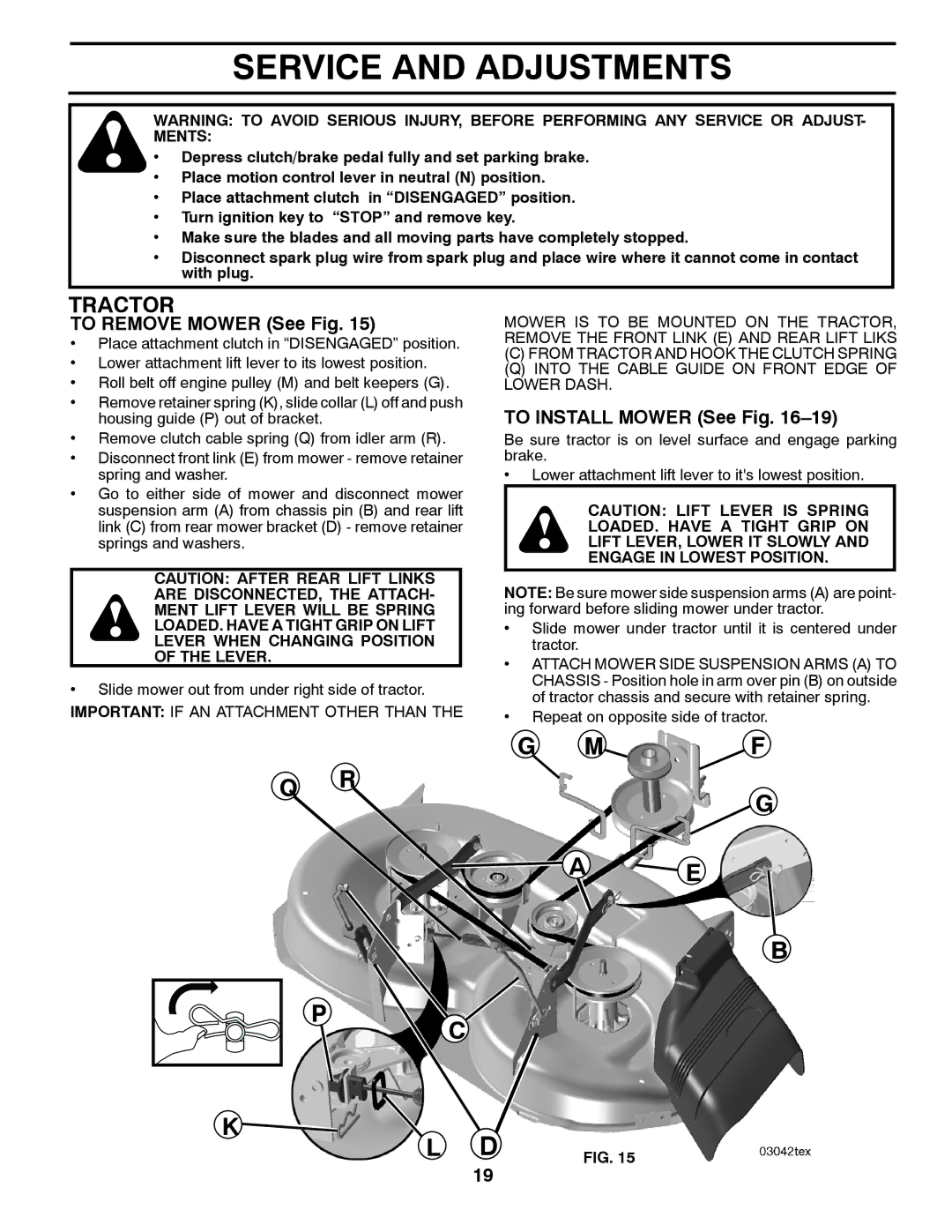
TO REMOVE MOWER (See Fig. 15)
•Place attachment clutch in “DISENGAGED” position.
•Lower attachment lift lever to its lowest position.
•Roll belt off engine pulley (M) and belt keepers (G).
•Remove retainer spring (K), slide collar (L) off and push housing guide (P) out of bracket.
•Remove clutch cable spring (Q) from idler arm (R).
•Disconnect front link (E) from mower - remove retainer spring and washer.
•Go to either side of mower and disconnect mower suspension arm (A) from chassis pin (B) and rear lift link (C) from rear mower bracket (D) - remove retainer springs and washers.
CAUTION: AFTER REAR LIFT LINKS
ARE DISCONNECTED, THE ATTACH-
MENT LIFT LEVER WILL BE SPRING
LOADED. HAVE A TIGHT GRIP ON LIFT
LEVER WHEN CHANGING POSITION
OF THE LEVER.
•Slide mower out from under right side of tractor.
IMPORTANT: IF AN ATTACHMENT OTHER THAN THE
MOWER IS TO BE MOUNTED ON THE TRACTOR, REMOVE THE FRONT LINK (E) AND REAR LIFT LIKS
(C)FROM TRACTOR AND HOOK THE CLUTCH SPRING
(Q)INTO THE CABLE GUIDE ON FRONT EDGE OF LOWER DASH.
TO INSTALL MOWER (See Fig. 16–19)
Be sure tractor is on level surface and engage parking brake.
•Lower attachment lift lever to it's lowest position.
CAUTION: LIFT LEVER IS SPRING
LOADED. HAVE A TIGHT GRIP ON
LIFT LEVER, LOWER IT SLOWLY AND
ENGAGE IN LOWEST POSITION.
NOTE: Be sure mower side suspension arms (A) are point- ing forward before sliding mower under tractor.
•Slide mower under tractor until it is centered under tractor.
•ATTACH MOWER SIDE SUSPENSION ARMS (A) TO CHASSIS - Position hole in arm over pin (B) on outside of tractor chassis and secure with retainer spring.
•Repeat on opposite side of tractor.
G M![]() F
F
Q RG
A E
B
P C
K | D |
|
L | FIG. 15 |
19