ASSEMBLY / PRE-OPERATION
INSTALL AUGER CONTROL ROD (See Figs. 5 and 6)
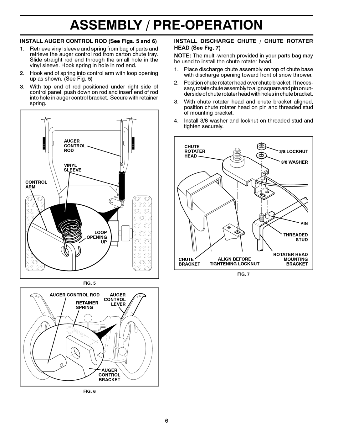
1.Retrieve vinyl sleeve and spring from bag of parts and retrieve the auger control rod from carton chute tray. Slide straight rod end through the small hole in the vinyl sleeve. Hook spring in hole in rod end.
2.Hook end of spring into control arm with loop opening up as shown. (See Fig. 5)
3.With top end of rod positioned under right side of control panel, push down on rod and insert end of rod into hole in auger control bracket. Secure with retainer spring.
AUGER |
CONTROL |
ROD |
VINYL |
SLEEVE |
CONTROL |
ARM |
LOOP |
OPENING |
UP |
FIG. 5
AUGER CONTROL ROD | AUGER | |
RETAINER | CONTROL | |
LEVER | ||
SPRING | ||
| ||
| AUGER | |
CONTROL | ||
BRACKET | ||
FIG. 6
INSTALL DISCHARGE CHUTE / CHUTE ROTATER HEAD (See Fig. 7)
NOTE: The
1.Place discharge chute assembly on top of chute base with discharge opening toward front of snow thrower.
2.Position chute rotater head over chute bracket. If neces- sary, rotatechute assembly to align square and pin on un- derside of chute rotater head with holes in chute bracket.
3.With chute rotater head and chute bracket aligned, position chute rotater head on pin and threaded stud of mounting bracket.
4.Install 3/8 washer and locknut on threaded stud and tighten securely.
CHUTE |
|
|
ROTATER |
| 3/8 LOCKNUT |
HEAD |
|
|
|
| 3/8 WASHER |
|
| PIN |
|
| THREADED |
|
| STUD |
| ALIGN BEFORE | ROTATER HEAD |
CHUTE | MOUNTING | |
BRACKET | TIGHTENING LOCKNUT | BRACKET |
FIG. 7
6