OPERATION
KNOW YOUR BRUSHCUTTER ATTACHMENT
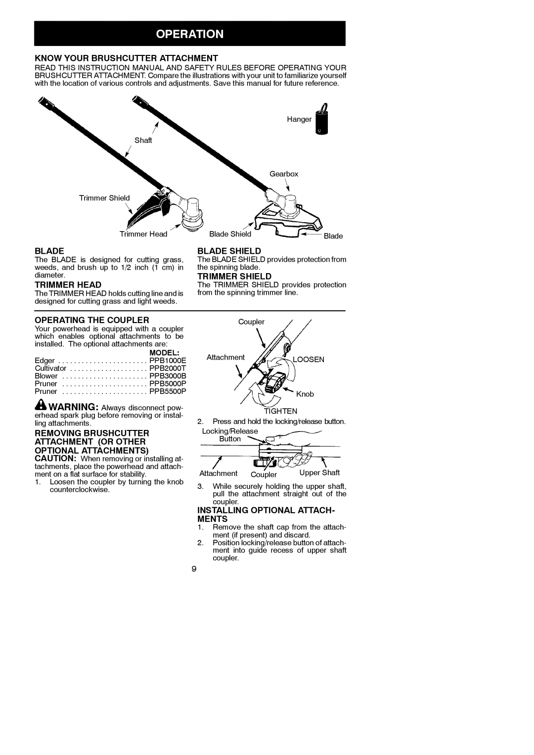
READ THIS INSTRUCTION MANUAL AND SAFETY RULES BEFORE OPERATING YOUR BRUSHCUTTER ATTACHMENT. Compare the illustrations with your unit to familiarize yourself with the location of various controls and adjustments. Save this manual for future reference.
| Hanger |
|
Shaft |
|
|
| Gearbox |
|
Trimmer Shield |
|
|
Trimmer Head | Blade Shield | Blade |
BLADE | BLADE SHIELD |
|
The BLADE is designed for cutting grass, | The BLADE SHIELD provides protection from | |
weeds, and brush up to 1/2 inch (1 cm) in | the spinning blade. |
|
diameter. | TRIMMER SHIELD |
|
TRIMMER HEAD | The TRIMMER SHIELD provides protection | |
The TRIMMER HEAD holds cutting line and is | from the spinning trimmer line. |
|
designed for cutting grass and light weeds.
OPERATING THE COUPLER |
| Coupler |
| |
Your powerhead is equipped with a coupler |
|
|
| |
which enables optional attachments to be |
|
|
| |
installed. The optional attachments are: |
|
|
| |
MODEL: |
| Attachment | LOOSEN | |
Edger . . . . . . . . . . . . . . . . . . . . . . . PPB1000E |
| |||
Cultivator . . . . . . . . . . . . . . . . . . . . PPB2000T |
|
|
| |
Blower . . . . . . . . . . . . . . . . . . . . . . PPB3000B |
|
|
| |
Pruner . . . . . . . . . . . . . . . . . . . . . . PPB5000P |
|
|
| |
Pruner . . . . . . . . . . . . . . . . . . . . . . PPB5500P |
|
| Knob | |
|
|
| ||
WARNING: Always disconnect pow- |
| TIGHTEN | ||
erhead spark plug before removing or instal- |
| |||
2. Press and hold the locking/release button. | ||||
ling attachments. | ||||
REMOVING BRUSHCUTTER | Locking/Release |
| ||
ATTACHMENT (OR OTHER |
| Button |
| |
OPTIONAL ATTACHMENTS) |
|
|
| |
CAUTION: When removing or installing at- |
|
|
| |
tachments, place the powerhead and attach- | Attachment Coupler | Upper Shaft | ||
ment on a flat surface for stability. | ||||
1. Loosen the coupler by turning the knob | 3. | While securely holding the upper shaft, | ||
counterclockwise. | ||||
| pull the attachment straight out of the | |||
|
| |||
|
| coupler. |
| |
| INSTALLING OPTIONAL ATTACH- | |||
| MENTS |
| ||
| 1. Remove the shaft cap from the attach- | |||
|
| ment (if present) and discard. | ||
| 2. | Position locking/release button of attach- | ||
|
| ment into guide recess of upper shaft | ||
|
| coupler. |
| |
| 9 |
|
| |