Cutter
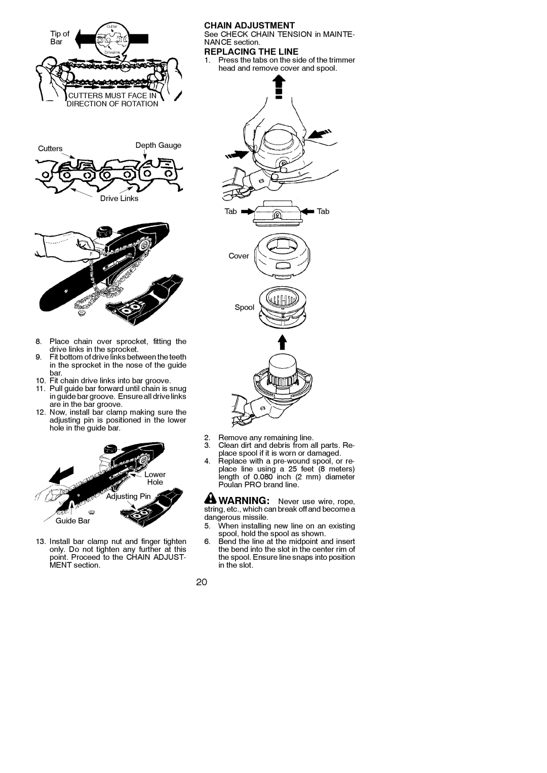
Tip of
Bar
Drivelink
CUTTERS MUST FACE IN
DIRECTION OF ROTATION
Cutters | Depth Gauge |
|
Drive Links
8.Place chain over sprocket, fitting the drive links in the sprocket.
9.Fit bottom of drive links between the teeth in the sprocket in the nose of the guide bar.
10.Fit chain drive links into bar groove.
11.Pull guide bar forward until chain is snug in guide bar groove. Ensure all drive links are in the bar groove.
12.Now, install bar clamp making sure the adjusting pin is positioned in the lower hole in the guide bar.
![]() Lower
Lower
Hole
Adjusting Pin
Guide Bar
13.Install bar clamp nut and finger tighten only. Do not tighten any further at this point. Proceed to the CHAIN ADJUST- MENT section.
CHAIN ADJUSTMENT
See CHECK CHAIN TENSION in MAINTE- NANCE section.
REPLACING THE LINE
1.Press the tabs on the side of the trimmer head and remove cover and spool.
TabTab
Cover
Spool
2.Remove any remaining line.
3.Clean dirt and debris from all parts. Re- place spool if it is worn or damaged.
4.Replace with a
![]() WARNING: Never use wire, rope, string, etc., which can break off and become a dangerous missile.
WARNING: Never use wire, rope, string, etc., which can break off and become a dangerous missile.
5.When installing new line on an existing spool, hold the spool as shown.
6.Bend the line at the midpoint and insert the bend into the slot in the center rim of the spool. Ensure line snaps into position in the slot.
20