1 REAR MOUNTING BRACKET and

SUPPORT TUBE

(See Figs. 1A, 1B & 1C)

Use Hardware - - GROUP "A"

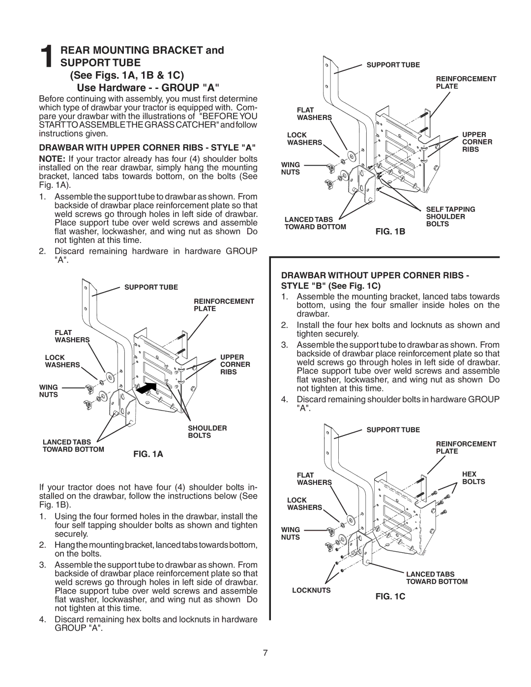
Before continuing with assembly, you must first determine which type of drawbar your tractor is equipped with. Com- pare your drawbar with the illustrations of "BEFORE YOU STARTTO ASSEMBLETHE GRASS CATCHER" and follow instructions given.

DRAWBAR WITH UPPER CORNER RIBS - STYLE "A"

NOTE: If your tractor already has four (4) shoulder bolts installed on the rear drawbar, simply hang the mounting bracket, lanced tabs towards bottom, on the bolts (See Fig. 1A).

1.Assemble the support tube to drawbar as shown. From backside of drawbar place reinforcement plate so that weld screws go through holes in left side of drawbar. Place support tube over weld screws and assemble flat washer, lockwasher, and wing nut as shown Do not tighten at this time.

2.Discard remaining hardware in hardware GROUP "A".


SUPPORT TUBE


REINFORCEMENT


PLATE

FLAT


WASHERS


LOCK

UPPER

WASHERS

CORNER


RIBS


SUPPORT TUBE


REINFORCEMENT


PLATE

FLAT


WASHERS


LOCK

UPPER

WASHERS

CORNER


RIBS

WING


NUTS


02352


SELF TAPPING

LANCED TABS

SHOULDER

BOLTS

TOWARD BOTTOM

FIG. 1B


DRAWBAR WITHOUT UPPER CORNER RIBS - STYLE "B" (See Fig. 1C)

1.

Assemble the mounting bracket, lanced tabs towards


bottom, using the four smaller inside holes on the


drawbar.

2.

Install the four hex bolts and locknuts as shown and


tighten securely.

3.

Assemble the support tube to drawbar as shown. From


backside of drawbar place reinforcement plate so that


weld screws go through holes in left side of drawbar.


Place support tube over weld screws and assemble


flat washer, lockwasher, and wing nut as shown Do

WING

NUTS

LANCED TABS TOWARD BOTTOM


3

5

4

02


SHOULDER

BOLTS

FIG. 1A

not tighten at this time.

4. Discard remaining shoulder bolts in hardware GROUP

"A".

SUPPORT TUBE

REINFORCEMENT

PLATE

If your tractor does not have four (4) shoulder bolts in- stalled on the drawbar, follow the instructions below (See Fig. 1B).

1.Using the four formed holes in the drawbar, install the four self tapping shoulder bolts as shown and tighten securely.

2.Hang the mounting bracket, lanced tabs towards bottom, on the bolts.

3.Assemble the support tube to drawbar as shown. From backside of drawbar place reinforcement plate so that weld screws go through holes in left side of drawbar. Place support tube over weld screws and assemble flat washer, lockwasher, and wing nut as shown Do not tighten at this time.

4.Discard remaining hex bolts and locknuts in hardware GROUP "A".

FLAT

HEX

WASHERS

BOLTS

LOCK

WASHERS

WING

NUTS

023

53


LANCED TABS TOWARD BOTTOM

LOCKNUTS

FIG. 1C

7

Page 7
Image 7
Poulan 954 04 05-03, C342B, 156235 Rear Mounting Bracket, Support Tube, See Figs A, 1B & 1C Use Hardware - Group a

156235, 954 04 05-03, C342B specifications

The Poulan 954 04 05-03, C342B, 156235 is a highly innovative and efficient tool that stands out in the realm of outdoor power equipment. Known for its durability and reliability, this model is designed for both professional landscapers and home gardeners. It incorporates advanced features and technologies that make yard maintenance tasks easier and more efficient.

One of the main features of the Poulan 954 04 05-03 is its robust engine performance. The powerful engine ensures that users can tackle even the most challenging tasks with ease. The design minimizes vibrations, providing a smoother operational experience, which is essential when using the tool for extended periods. This engine is also designed to enhance fuel efficiency, allowing longer working times between refuels.

Another notable characteristic is the ergonomic design of the tool. The handle is crafted for comfort, featuring a grip that reduces fatigue. Additionally, the balanced weight distribution of the tool helps in maneuverability, making it easier to handle during intensive jobs whether trimming hedges or maintaining lawns.

The Poulan C342B model is recognized for integrating advanced technologies that set it apart from competitors. It features a reliable starter system that ensures easy starts, even in cold weather conditions. This is particularly convenient for users who need to get to work quickly without the frustration of a traditional pull-start system.

Moreover, the Poulan 956 04 05-03 incorporates an adjustable cutting height feature, allowing users to customize the cutting length based on specific gardening needs. This flexibility makes it suitable for various grass types and landscaping designs, ensuring a healthy lawn while allowing creativity in outdoor spaces.

Durability is another strong point for this model. Constructed from high-quality materials, the Poulan 954 04 05-03 is designed to withstand harsh weather conditions and the rigors of frequent use. This resilience contributes to a longer lifespan and a lower overall maintenance requirement.

In summary, the Poulan 954 04 05-03, C342B, 156235 combines powerful performance, user-friendly design, and advanced technology, making it an excellent choice for anyone looking to invest in a dependable outdoor power tool. With its blend of innovation and functionality, users can expect superior results in their gardening and landscaping efforts, ensuring their outdoor spaces remain pristine and well-maintained.