Powermate P1204 owner manual Utility Circuit Supply, Generator Start Signal

Models: P1204

1 32
Download 32 pages 63.69 Kb
Page 12
Image 12

UTILITY CIRCUIT SUPPLY

A receptacle is provided with the generator to power the battery charger for reliable starting. It is also intended to power an optional block heater if that option is desired. Connection of this circuit to a power supply that is only present when normal utility power is supplied is recommended. By connecting the receptacle in this fashion, it is possible to insure that neither the battery charger or block heater are on while the engine is running. Precautions are engineered into the generator to prevent these occurances but connection of the circuit in this fashion provides an additional fail-safe method of engine and battery protection.

Input to the utility circuit is 3-wire, 120V, 15A. Connections include a "hot" lead (L1), neutral (N) and ground lead. Positions of the incoming wire connections are labeled at the auxiliary connection block, shown in Fig. B . Select proper utility supply wire size according to allowable ampacities given in Table 310-16 of the latest revision of The National Electric Code(NFPA 70). To connect the wires, strip the insulation back approximately ¼" from the end of the wire, insert the stripped end under the screw and washer on the terminal block, then torque the terminal block screw to 20 in-lbs (2.3 N-m).

GENERATOR START SIGNAL

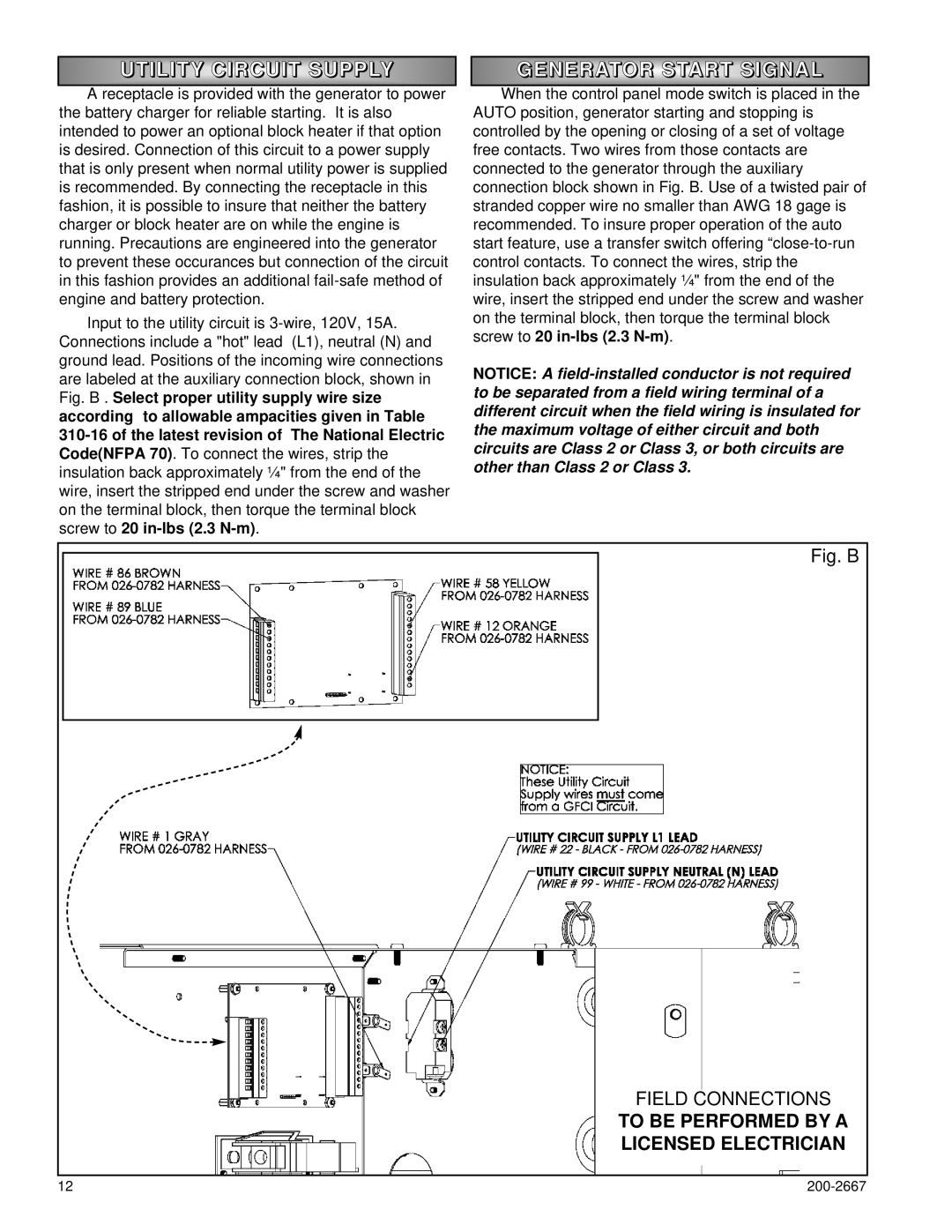
When the control panel mode switch is placed in the AUTO position, generator starting and stopping is controlled by the opening or closing of a set of voltage free contacts. Two wires from those contacts are connected to the generator through the auxiliary connection block shown in Fig. B. Use of a twisted pair of stranded copper wire no smaller than AWG 18 gage is recommended. To insure proper operation of the auto start feature, use a transfer switch offering “close-to-run control contacts. To connect the wires, strip the insulation back approximately ¼" from the end of the wire, insert the stripped end under the screw and washer on the terminal block, then torque the terminal block screw to 20 in-lbs (2.3 N-m).

NOTICE: A field-installed conductor is not required to be separated from a field wiring terminal of a different circuit when the field wiring is insulated for the maximum voltage of either circuit and both circuits are Class 2 or Class 3, or both circuits are other than Class 2 or Class 3.

Fig. B

FIELD CONNECTIONS

TO BE PERFORMED BY A

LICENSED ELECTRICIAN

12

200-2667

Page 12
Image 12
Powermate P1204 owner manual Utility Circuit Supply, Generator Start Signal