MAJOR GENERATOR FEATURES |
| PORTABILITY KIT INSTALLATION |
|
|
|
*10 HP Briggs & Stratton OHV engine
*Low oil sensor
*Receptacles on control panel
*6 gallon plastic fuel tank
*Portability Kit
CONTROL PANEL
A.120 V, 20 Ampere Duplex Receptacle
This duplex is split so that 20 amps of current may be
drawn from each half of the receptacle. However, total power drawn must be kept within nameplate ratings. These receptacles may be used along with the twistlock receptacle provided the generator is not overloaded.
B.120/240 V, 20 Ampere Twistlock Receptacle
A maximum of 20 amps may be drawn from the 120/240
volt receptacle, provided it is the only receptacle used. However, current must be limited to the nameplate rating. If the 120/240 volt receptacle is used along with the 120 volt receptacle, the total load drawn must not exceed the nameplate ratings.
C.Circuit Breakers
The receptacles are protected by an AC circuit breaker. If the generator is overloaded or an external short circuit occurs, the circuit breaker will trip. If this occurs, disconnect all electrical loads and try to determine the cause of the problem before attempting to use the generator again. If overloading causes the circuit breaker to trip, reduce the load. NOTE:
Continuous tripping of the circuit breaker may cause damage to generator or equipment. The circuit breaker may be reset by pushing the button of the breaker.
TOOLS REQUIRED: 1/2” and 9/16" sockets and ratchets, block(s) of wood (minimum of 6” tall).
Refer to the parts list and drawing on pages 8 and 9.
WHEEL INSTALLATION
1.Block up end of generator opposite the fuel tank cap to install wheel kit.
2.Insert wheel spacer (item 43) into the center of the wheel
(item 35).
3.Slide 3/8 x 3.5” bolt (item 41) through the wheel (item 35), then through the wheel bracket on the carrier, with the offset side of the wheel hub against the wheel bracket.
4.Thread 3/8 nyloc nut (item 42) onto the bolt and tighten to securely clamp the wheel assembly to the tubing.
5.Repeat above instructions for the remaining wheel.
FOOT INSTALLATION
1.Blocking up the engine side of the generator, place a spacer (item 38) and a foot (item 37) under the carrier channel. Thread a
2.Repeat step 1 for the remaining foot.
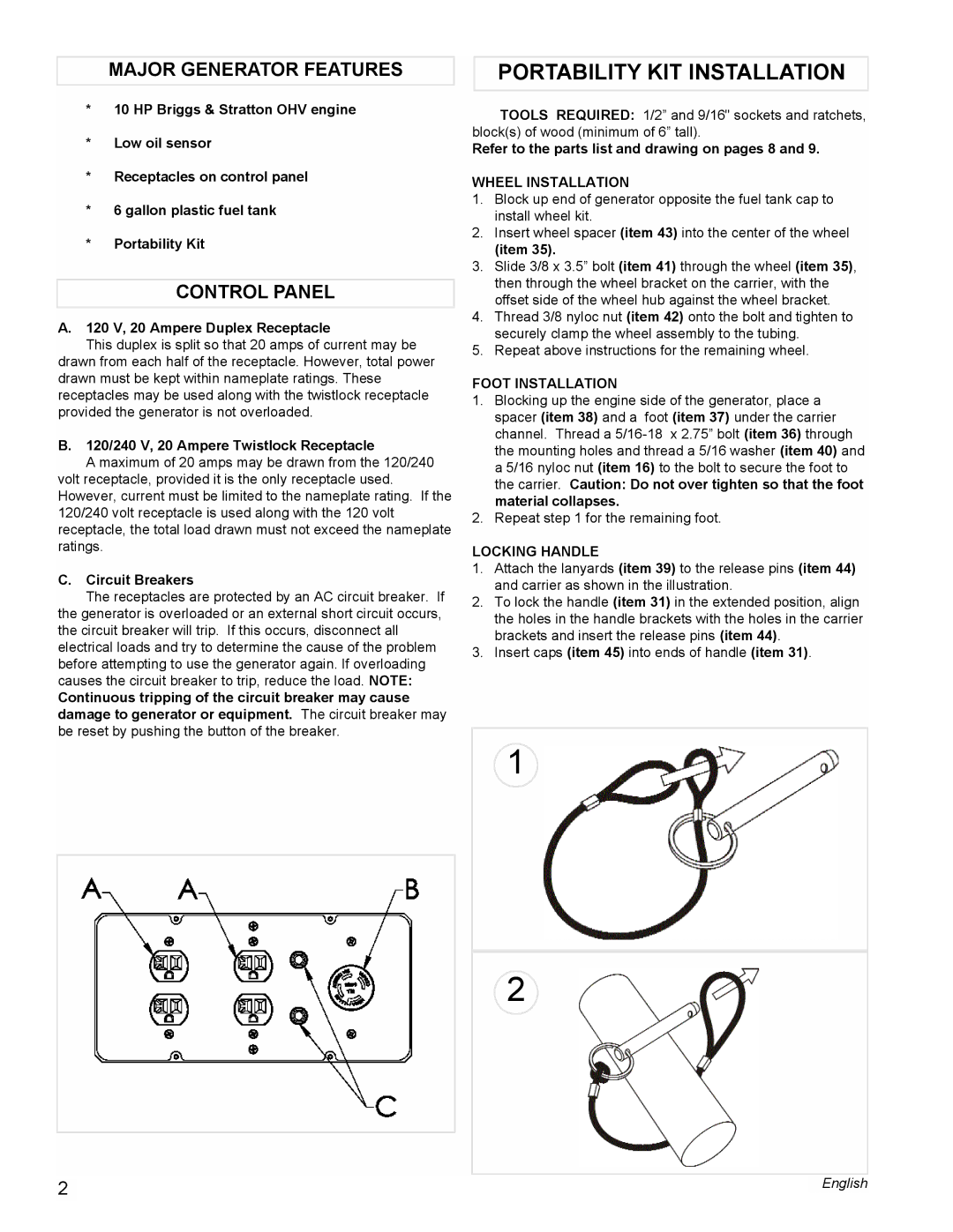
LOCKING HANDLE
1.Attach the lanyards (item 39) to the release pins (item 44) and carrier as shown in the illustration.
2.To lock the handle (item 31) in the extended position, align the holes in the handle brackets with the holes in the carrier brackets and insert the release pins (item 44).
3.Insert caps (item 45) into ends of handle (item 31).
1
2
|
| English | |
2 | |||
|
|