MAJOR GENERATOR FEATURES |
| ELECTRIC START |
|
|
|
*16 HP Tecumseh OHV engine
*
*Low oil sensor
*Receptacles on control panel
*Electric start
*7 gallon plastic fuel tank
*Portability Kit
CONTROL PANEL
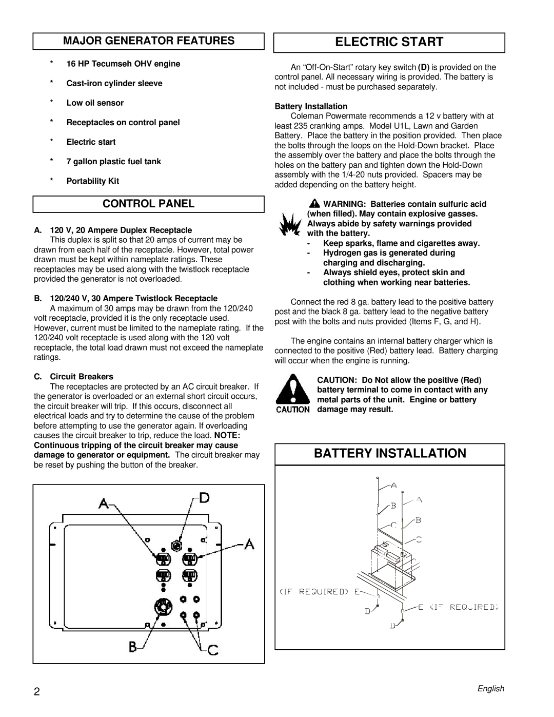
A.120 V, 20 Ampere Duplex Receptacle
This duplex is split so that 20 amps of current may be
drawn from each half of the receptacle. However, total power drawn must be kept within nameplate ratings. These receptacles may be used along with the twistlock receptacle provided the generator is not overloaded.
B. 120/240 V, 30 Ampere Twistlock Receptacle
A maximum of 30 amps may be drawn from the 120/240 volt receptacle, provided it is the only receptacle used. However, current must be limited to the nameplate rating. If the 120/240 volt receptacle is used along with the 120 volt receptacle, the total load drawn must not exceed the nameplate ratings.
C. Circuit Breakers
The receptacles are protected by an AC circuit breaker. If the generator is overloaded or an external short circuit occurs, the circuit breaker will trip. If this occurs, disconnect all electrical loads and try to determine the cause of the problem before attempting to use the generator again. If overloading causes the circuit breaker to trip, reduce the load. NOTE:
Continuous tripping of the circuit breaker may cause damage to generator or equipment. The circuit breaker may be reset by pushing the button of the breaker.
An
Battery Installation
Coleman Powermate recommends a 12 v battery with at least 235 cranking amps. Model U1L, Lawn and Garden Battery. Place the battery in the position provided. Then place the bolts through the loops on the
![]() WARNING: Batteries contain sulfuric acid (when filled). May contain explosive gasses. Always abide by safety warnings provided with the battery.
WARNING: Batteries contain sulfuric acid (when filled). May contain explosive gasses. Always abide by safety warnings provided with the battery.
-Keep sparks, flame and cigarettes away.
-Hydrogen gas is generated during charging and discharging.
-Always shield eyes, protect skin and clothing when working near batteries.
Connect the red 8 ga. battery lead to the positive battery post and the black 8 ga. battery lead to the negative battery post with the bolts and nuts provided (Items F, G, and H).
The engine contains an internal battery charger which is connected to the positive (Red) battery lead. Battery charging will occur when the engine is running.
CAUTION: Do Not allow the positive (Red) battery terminal to come in contact with any metal parts of the unit. Engine or battery damage may result.
BATTERY INSTALLATION
2 | English |