5.Now place the board flush against the fence and against the rail of the roller table(s). If necessary, shift a roller table horizontally to bring it in line with the fence.
6.When final adjustments have been made and
CAUTION: Never adjust the outfeed table level higher than the level of the machine table surface.
ADJUSTMENTS
WARNING: Disconnect all power sources, both air and electric, prior to making adjustments.
BLADE TRAVEL
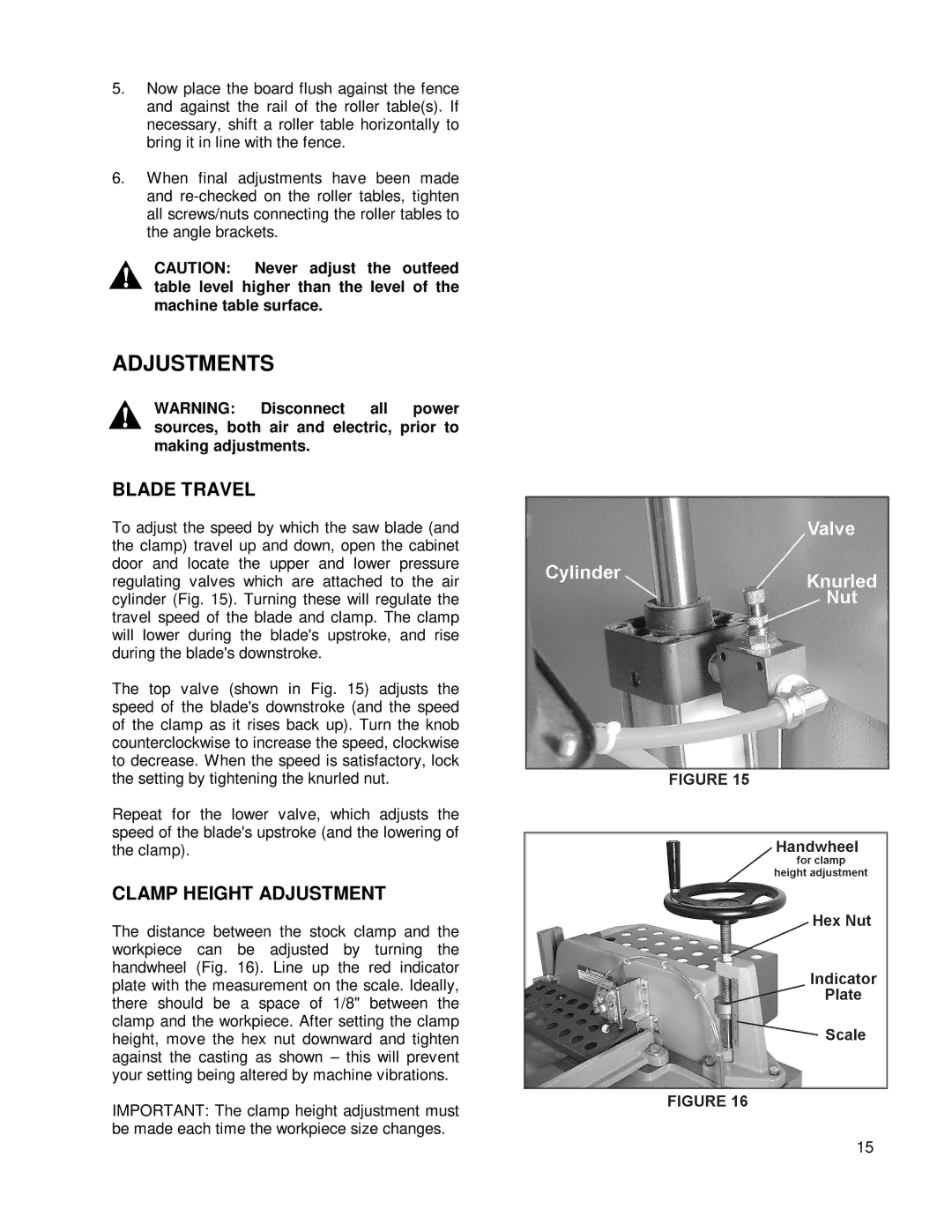
To adjust the speed by which the saw blade (and the clamp) travel up and down, open the cabinet door and locate the upper and lower pressure regulating valves which are attached to the air cylinder (Fig. 15). Turning these will regulate the travel speed of the blade and clamp. The clamp will lower during the blade's upstroke, and rise during the blade's downstroke.
The top valve (shown in Fig. 15) adjusts the speed of the blade's downstroke (and the speed of the clamp as it rises back up). Turn the knob counterclockwise to increase the speed, clockwise to decrease. When the speed is satisfactory, lock the setting by tightening the knurled nut.
Repeat for the lower valve, which adjusts the speed of the blade's upstroke (and the lowering of the clamp).
CLAMP HEIGHT ADJUSTMENT
The distance between the stock clamp and the workpiece can be adjusted by turning the handwheel (Fig. 16). Line up the red indicator plate with the measurement on the scale. Ideally, there should be a space of 1/8" between the clamp and the workpiece. After setting the clamp height, move the hex nut downward and tighten against the casting as shown – this will prevent your setting being altered by machine vibrations.
IMPORTANT: The clamp height adjustment must be made each time the workpiece size changes.
15