Assembly
Mounting Extension Wings
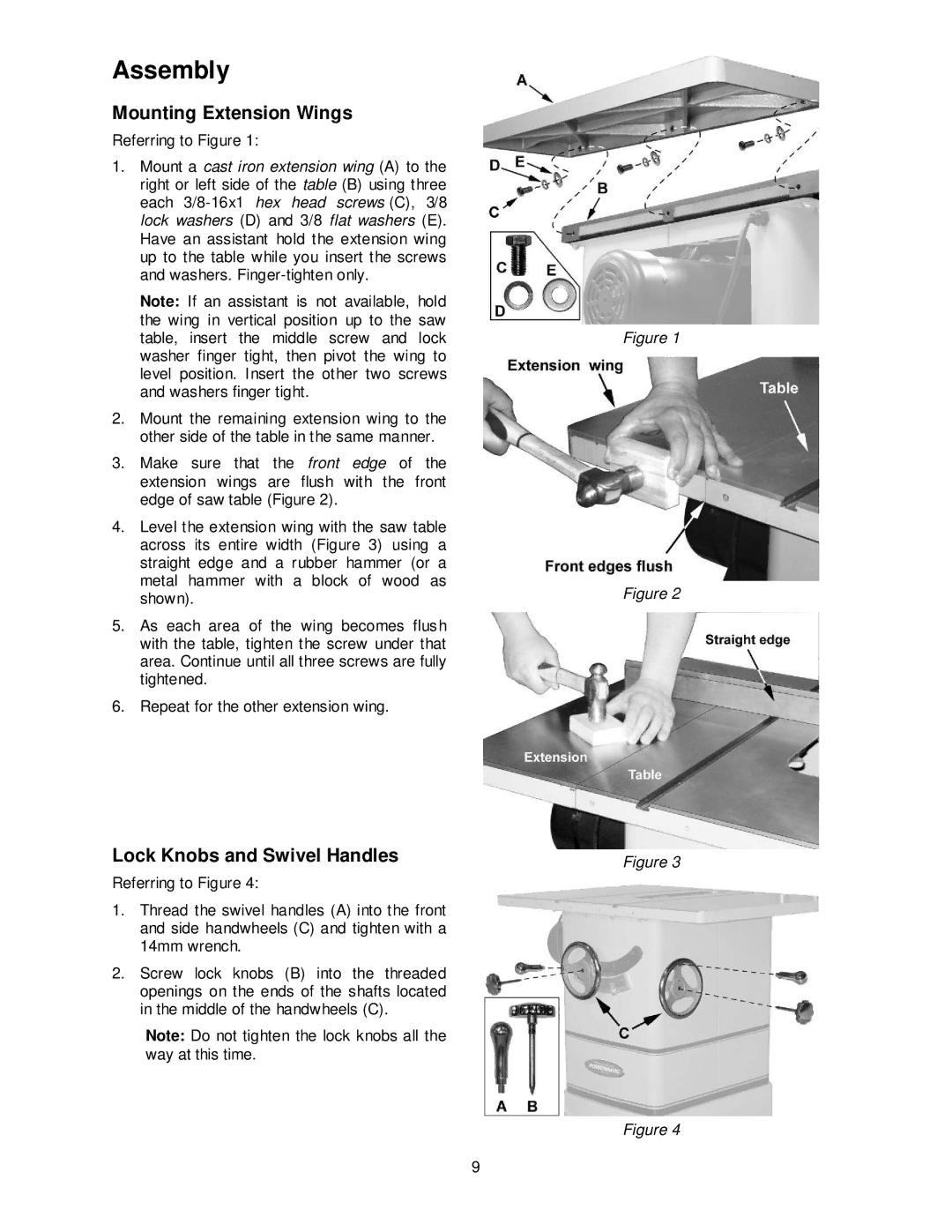
Referring to Figure 1:
1.Mount a cast iron extension wing (A) to the right or left side of the table (B) using three each
Note: If an assistant is not available, hold the wing in vertical position up to the saw table, insert the middle screw and lock washer finger tight, then pivot the wing to level position. Insert the other two screws and washers finger tight.
2.Mount the remaining extension wing to the other side of the table in the same manner.
3.Make sure that the front edge of the extension wings are flush with the front edge of saw table (Figure 2).
4.Level the extension wing with the saw table across its entire width (Figure 3) using a straight edge and a rubber hammer (or a metal hammer with a block of wood as shown).
5.As each area of the wing becomes flush with the table, tighten the screw under that area. Continue until all three screws are fully tightened.
6.Repeat for the other extension wing.
Lock Knobs and Swivel Handles
Referring to Figure 4:
1.Thread the swivel handles (A) into the front and side handwheels (C) and tighten with a 14mm wrench.
2.Screw lock knobs (B) into the threaded openings on the ends of the shafts located in the middle of the handwheels (C).
Note: Do not tighten the lock knobs all the way at this time.
Figure 1
Figure 2
Figure 3
Figure 4
9