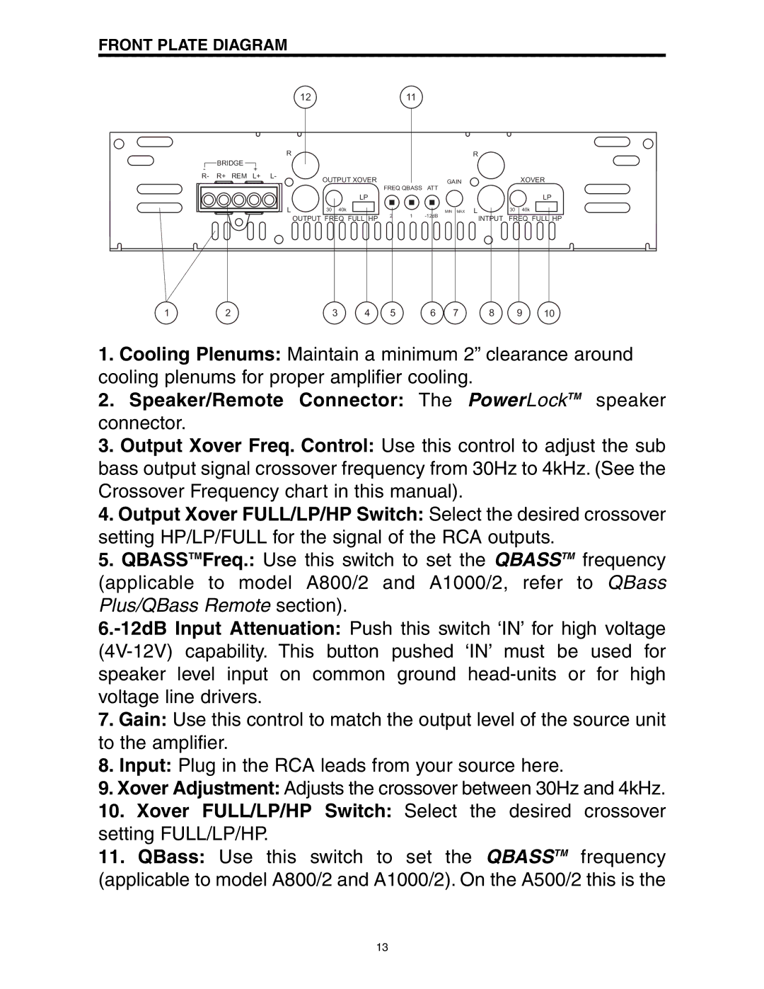
FRONT PLATE DIAGRAM
1211
R
BRIDGE
-+
R- R+ REM L+ L-
|
| R |
OUTPUT XOVER | GAIN | XOVER |
FREQ QBASS | ATT |
|
| LP |
|
|
| LP |
L | 30 40k | 2 | 1 | MIN MAX L | 30 40k |
| OUTPUT FREQ FULL HP | INTPUT | FREQ FULL HP | ||
|
|
|
1 | 2 | 3 | 4 | 5 | 6 | 7 | 8 | 9 | 10 |
1.Cooling Plenums: Maintain a minimum 2” clearance around cooling plenums for proper amplifier cooling.
2.Speaker/Remote Connector: The PowerLockTM speaker connector.
3.Output Xover Freq. Control: Use this control to adjust the sub bass output signal crossover frequency from 30Hz to 4kHz. (See the Crossover Frequency chart in this manual).
4.Output Xover FULL/LP/HP Switch: Select the desired crossover setting HP/LP/FULL for the signal of the RCA outputs.
5.QBASSTMFreq.: Use this switch to set the QBASSTM frequency (applicable to model A800/2 and A1000/2, refer to QBass Plus/QBass Remote section).
7.Gain: Use this control to match the output level of the source unit to the amplifier.
8.Input: Plug in the RCA leads from your source here.
9.Xover Adjustment: Adjusts the crossover between 30Hz and 4kHz.
10.Xover FULL/LP/HP Switch: Select the desired crossover setting FULL/LP/HP.
11.QBass: Use this switch to set the QBASSTM frequency (applicable to model A800/2 and A1000/2). On the A500/2 this is the
13