DCX 800.5 FRONT PLATE DIAGRAM
12
DCX 800.5 | 21 | 20 | 19 | 18 | 17 | 16 | 15 | 14 | 13 | 11 | 10 |
Front Panel |
|
|
|
|
|
|
|
|
|
|
|
FREQ | GAIN | SUM | FREQ | GAIN | INT |
| FREQ | GAIN | ||||
|
|
|
| SUB |
|
|
|
| EXT | FULL/LP/HP |
|
|
30 | 4K | MIN | MAX |
| 30 | 4K | MIN | MAX |
| FULL/LP/HP | 30 4K | MIN MAX |
FULL/LP/HP |
| SUB |
| SOURCE | FULL/LP/HP |
| REAR |
| SOURCE | FRONT |
| SOURCE |
|
|
|
|
|
|
|
|
|
| |||
|
|
|
|
|
|
|
|
|
|
|
| ATT |
- |
| - | + |
| + | RR- |
| RR+ | RL+ |
| RL- | FR- | FR+ | REM FL+ | FL- |
|
|
| |||||||||||||||||||||
|
|
| SUB |
|
|
| BRIDGED |
|
|
|
|
|
|
|
|
|
| BRIDGED |
|
|
|
|
|
|
|
|
|
|
| ||||||||||
|
|
|
|
|
|
|
|
|
|
|
|
|
|
|
|
|
|
|
|
|
|
|
|
|
|
|
|
|
|
|
|
|
|
|
|
|
|
|
|
|
|
|
|
|
|
|
|
|
|
|
|
|
|
|
|
|
|
|
|
|
|
|
|
|
|
|
|
|
|
|
|
|
|
|
|
|
|
|
|
9
SUB | REAR | FRONT | QBASS FREQ | |
|
| R | ||
|
|
| 2 | 1 |
IN | IN | L |
|
|
IN |
|
| ||
1 | 2 | 3 | 4 | 5 | 6 | 7 | 8 |
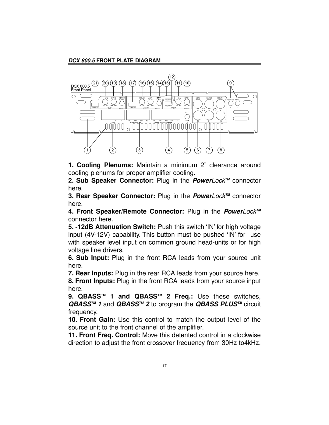
1.Cooling Plenums: Maintain a minimum 2” clearance around cooling plenums for proper amplifier cooling.
2.Sub Speaker Connector: Plug in the PowerLockTM connector here.
3.Rear Speaker Connector: Plug in the PowerLockTM connector here.
4.Front Speaker/Remote Connector: Plug in the PowerLockTM connector here.
5.
6.Sub Input: Plug in the front RCA leads from your source unit here.
7.Rear Inputs: Plug in the rear RCA leads from your source here.
8.Front Inputs: Plug in the front RCA leads from your source input here.
9.QBASSTM 1 and QBASSTM 2 Freq.: Use these switches, QBASSTM 1 and QBASSTM 2 to program the QBASS PLUSTM circuit frequency.
10.Front Gain: Use this control to match the output level of the source unit to the front channel of the amplifier.
11.Front Freq. Control: Move this detented control in a clockwise direction to adjust the front crossover frequency from 30Hz to4kHz.
17