to use the internal signal path from the front crossover for the rear input, or the EXT position to use the external rear RCA input.
13.Source HP/LP/FULL Switch: Select the desired setting. HP/LP/FULL for the internal signal from the front channel to the rear channel when not using an external rear RCA input.
14.Rear Gain: Use this control to match the output level of the head unit to the rear channel of the amplifier.
15.Rear Freq. Control: Move this detented control in a clockwise rotation to adjust the rear crossover frequency from 30Hz to 4kHz. (See the Crossover Frequency chart in this manual).
16.Rear HP/LP/FULL Switch: Select the desired crossover setting, HP/LP/FULL for the speaker output signal of the rear channel.
17.Source Sum/Rear Switch: Select the SUM position if you want to use the RCA output signal summed from the front and rear audio channels, or the REAR position to select the input off of the rear channel only for bandpass capability.
18.Source HP/LP/FULL Switch: Select the desired crossover setting. HP/LP/FULL for the output signal of the rear channel when not using the SUM source input.
19.Output Freq. Control: Use this control to adjust the rear high pass crossover frequency from 30Hz to 4kHz. (See the Crossover Frequency chart in this manual).
20.Output HP/LP/FULL Switch: Select the desired crossover setting. HP/LP/FULL for the signal of the output RCA.
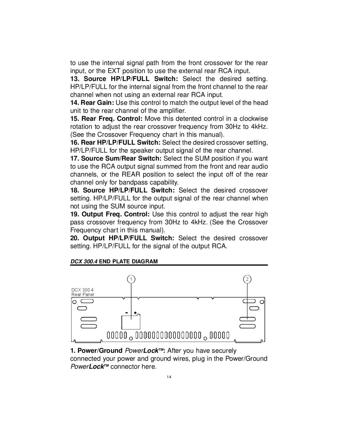
DCX 300.4 END PLATE DIAGRAM
1 | 2 |
DCX 300.4 |
|
Rear Panel |
|
1.Power/Ground PowerLockTM: After you have securely connected your power and ground wires, plug in the Power/Ground PowerLockTM connector here.
14