JVC 250 service manual Troubleshooting on the Backplane PCB, 17 Backplane Diagram left side, 7-26

Models: 250

1 190
Download 190 pages 59.74 Kb
Page 164
Image 164
Troubleshooting on the Backplane PCB

Chapter 7---Troubleshooting

Troubleshooting on the Backplane PCB

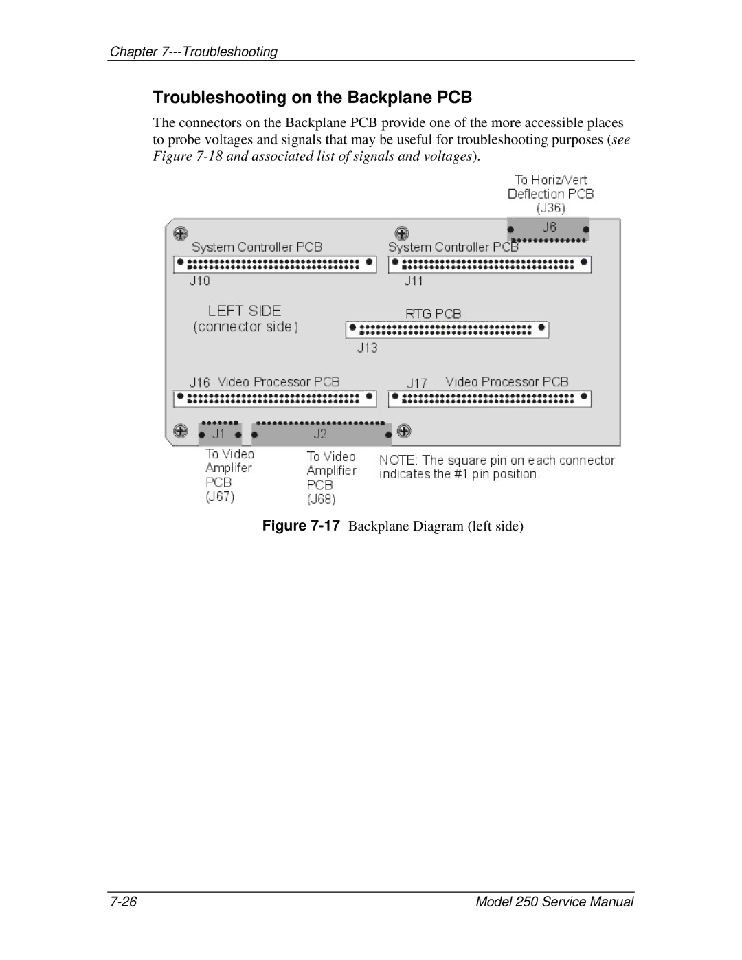
The connectors on the Backplane PCB provide one of the more accessible places to probe voltages and signals that may be useful for troubleshooting purposes (see Figure 7-18and associated list of signals and voltages).

Figure 7-17Backplane Diagram (left side)

7-26

Model 250 Service Manual

Page 164
Image 164
JVC service manual Troubleshooting on the Backplane PCB, 17 Backplane Diagram left side, 7-26, Model 250 Service Manual