Chapter 3---Electrical
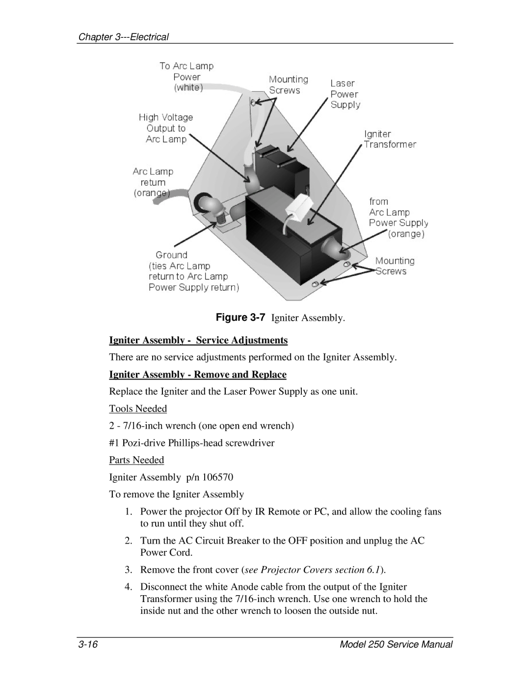
Figure 3-7 Igniter Assembly.
Igniter Assembly - Service Adjustments
There are no service adjustments performed on the Igniter Assembly.
Igniter Assembly - Remove and Replace
Replace the Igniter and the Laser Power Supply as one unit.
Tools Needed
2 -
#1
Parts Needed
Igniter Assembly p/n 106570
To remove the Igniter Assembly
1.Power the projector Off by IR Remote or PC, and allow the cooling fans to run until they shut off.
2.Turn the AC Circuit Breaker to the OFF position and unplug the AC Power Cord.
3.Remove the front cover (see Projector Covers section 6.1).
4.Disconnect the white Anode cable from the output of the Igniter Transformer using the
Model 250 Service Manual |