Chapter 5---Electronics
the V_PARAB waveform. The output waveform V_RGB+ goes to the Scan Reversal PCB and then drives the Vertical Deflection Yokes. The Vertical Deflection Yoke return signal to the Horizontal Vertical Deflection PCB is
Horizontal Vertical Deflection PCB - Service Adjustments
Vertical Size Adjustment
Tools Needed
Miniature
To adjust the Vertical height (see Figure
1.Remove the rear cover and pull the Interlock switch out to the Service Mode position.
2.Power ON the projector by IR Remote or PC, and allow it to stabilize for a minimum of 15 minutes
3.Use the
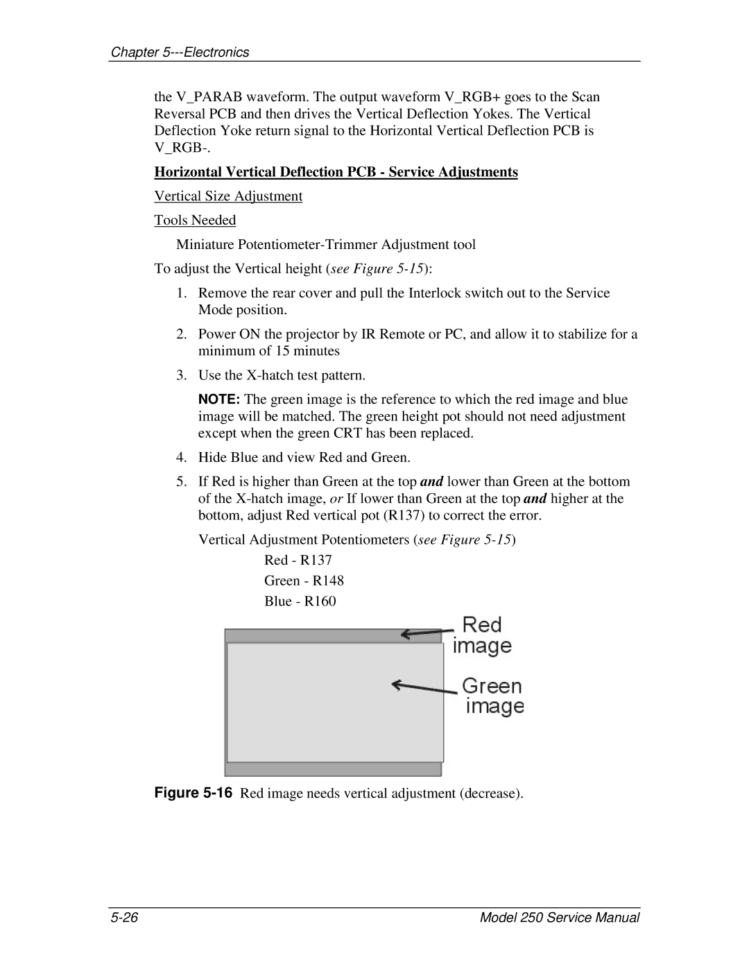
NOTE: The green image is the reference to which the red image and blue image will be matched. The green height pot should not need adjustment except when the green CRT has been replaced.
4.Hide Blue and view Red and Green.
5.If Red is higher than Green at the top and lower than Green at the bottom of the
Vertical Adjustment Potentiometers (see Figure
Green - R148 Blue - R160
Figure 5-16 Red image needs vertical adjustment (decrease).
Model 250 Service Manual |