Chapter 5---Electronics
6.Pull the black card extractor handles back to disconnect the Video Processor PCB connector and pull the PCB out of the Electronics Module.
7.Reverse the procedure to install the Video Processor PCB.
5.5Raster Timing Generator PCB
Raster Timing Generator PCB - Main Functions
!Generates an internal sync pulse
!Detects and selects sync pulses
!Generates a phase locked sync
!Generates blanking pulse
!Provides horizontal and vertical phase adjustments
!Detects interlaced and generates odd field pulse
!Selects horizontal frequency band
!Generates horizontal line count and vertical count
!Provides IIC interface
!Generates clamp pulse
!Detects changes in source
!Generates HVPS_SYNC signal
!Enables horizontal deflection (/H_ENA) circuitry
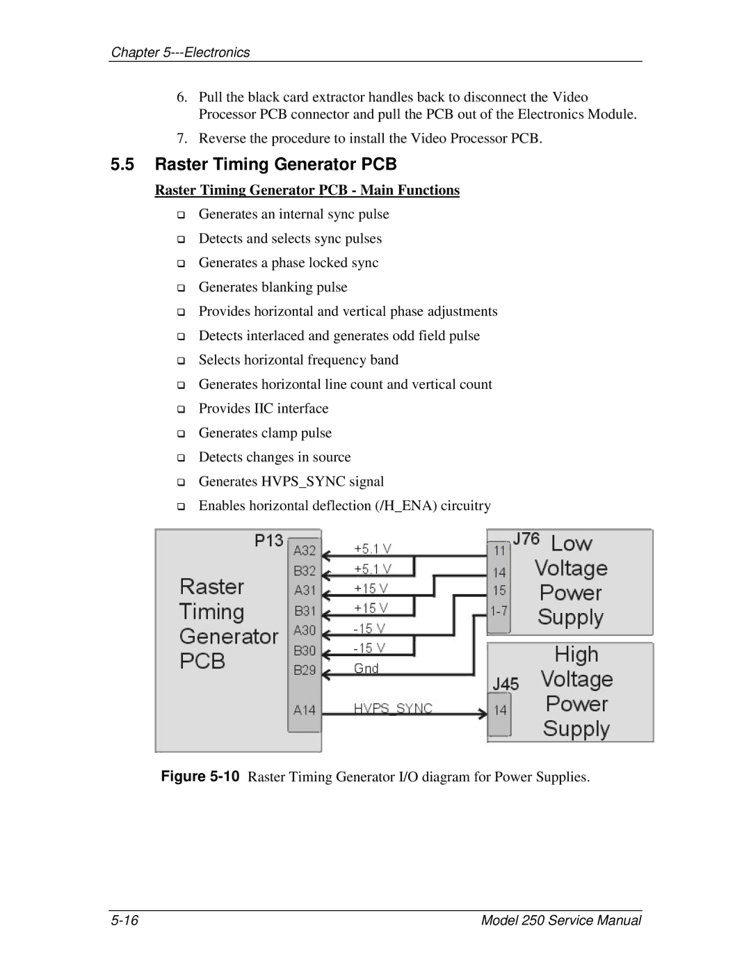
Figure 5-10 Raster Timing Generator I/O diagram for Power Supplies.
Model 250 Service Manual |