Chapter
 WARNING!!! Never look directly at the Arc Lamp, the lighted Projection Lens or into the lamp housing, from any distance, when the projector is on. Direct exposure to light of this brightness can cause severe eye injury.
5.2Introduction
The Model 250 Electronics System includes nine printed circuit assemblies. They provide all the controlling voltages and signals to adjust and correct picture settings, geometry, convergence, and shading (see Chapter 4 of the User’s Guide). The Electronics System also controls video and sync input signals, LED displays on PCBs at the rear and side of the projector, two
The descriptions in this portion of the manual are based on an overall Electronics System block diagram and simplified block diagrams for each of the nine printed circuit assemblies.
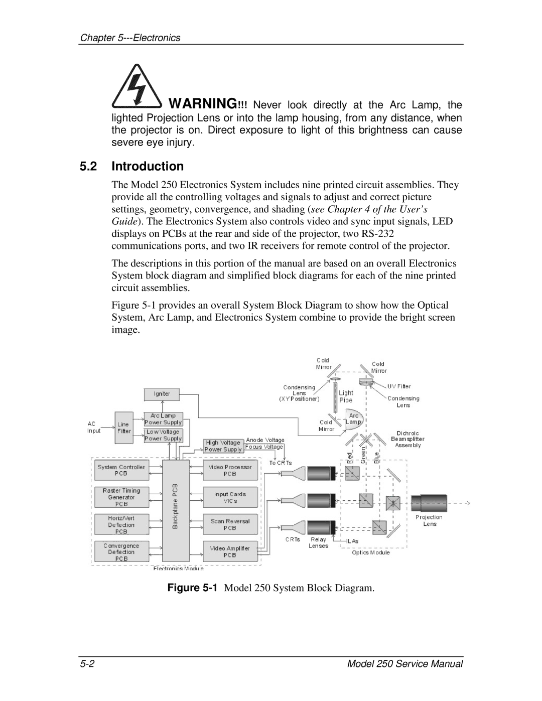
Figure 5-1 provides an overall System Block Diagram to show how the Optical System, Arc Lamp, and Electronics System combine to provide the bright screen image.
Figure 5-1 Model 250 System Block Diagram.
Model 250 Service Manual |