Chapter 7---Troubleshooting
CRT Protection
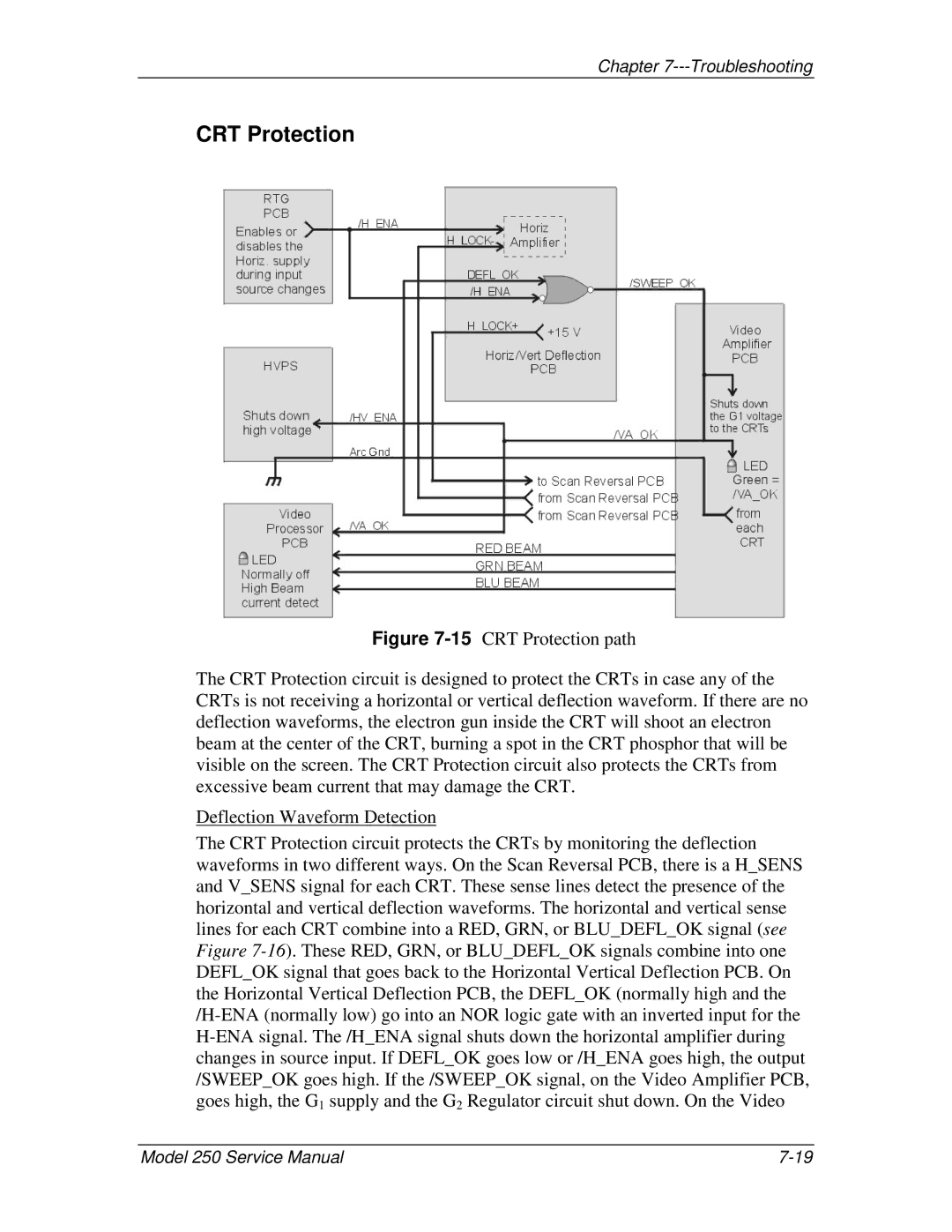
Figure 7-15 CRT Protection path
The CRT Protection circuit is designed to protect the CRTs in case any of the CRTs is not receiving a horizontal or vertical deflection waveform. If there are no deflection waveforms, the electron gun inside the CRT will shoot an electron beam at the center of the CRT, burning a spot in the CRT phosphor that will be visible on the screen. The CRT Protection circuit also protects the CRTs from excessive beam current that may damage the CRT.
Deflection Waveform Detection
The CRT Protection circuit protects the CRTs by monitoring the deflection waveforms in two different ways. On the Scan Reversal PCB, there is a H_SENS and V_SENS signal for each CRT. These sense lines detect the presence of the horizontal and vertical deflection waveforms. The horizontal and vertical sense lines for each CRT combine into a RED, GRN, or BLU_DEFL_OK signal (see Figure 7-16). These RED, GRN, or BLU_DEFL_OK signals combine into one DEFL_OK signal that goes back to the Horizontal Vertical Deflection PCB. On the Horizontal Vertical Deflection PCB, the DEFL_OK (normally high and the /H-ENA (normally low) go into an NOR logic gate with an inverted input for the H-ENA signal. The /H_ENA signal shuts down the horizontal amplifier during changes in source input. If DEFL_OK goes low or /H_ENA goes high, the output /SWEEP_OK goes high. If the /SWEEP_OK signal, on the Video Amplifier PCB, goes high, the G1 supply and the G2 Regulator circuit shut down. On the Video
Model 250 Service Manual |