Chapter 5---Electronics
4-Input (Quad) RGBHV VIC
4-Input (Quad) RGBHV VIC - Main Functions
!Interface for four sets of Red, Green, and Blue image inputs
!Interface for four sets of Horizontal and Vertical synchronization pulses
!VIC selection by IIC Serial Data Bus
!LED indication of VIC selection
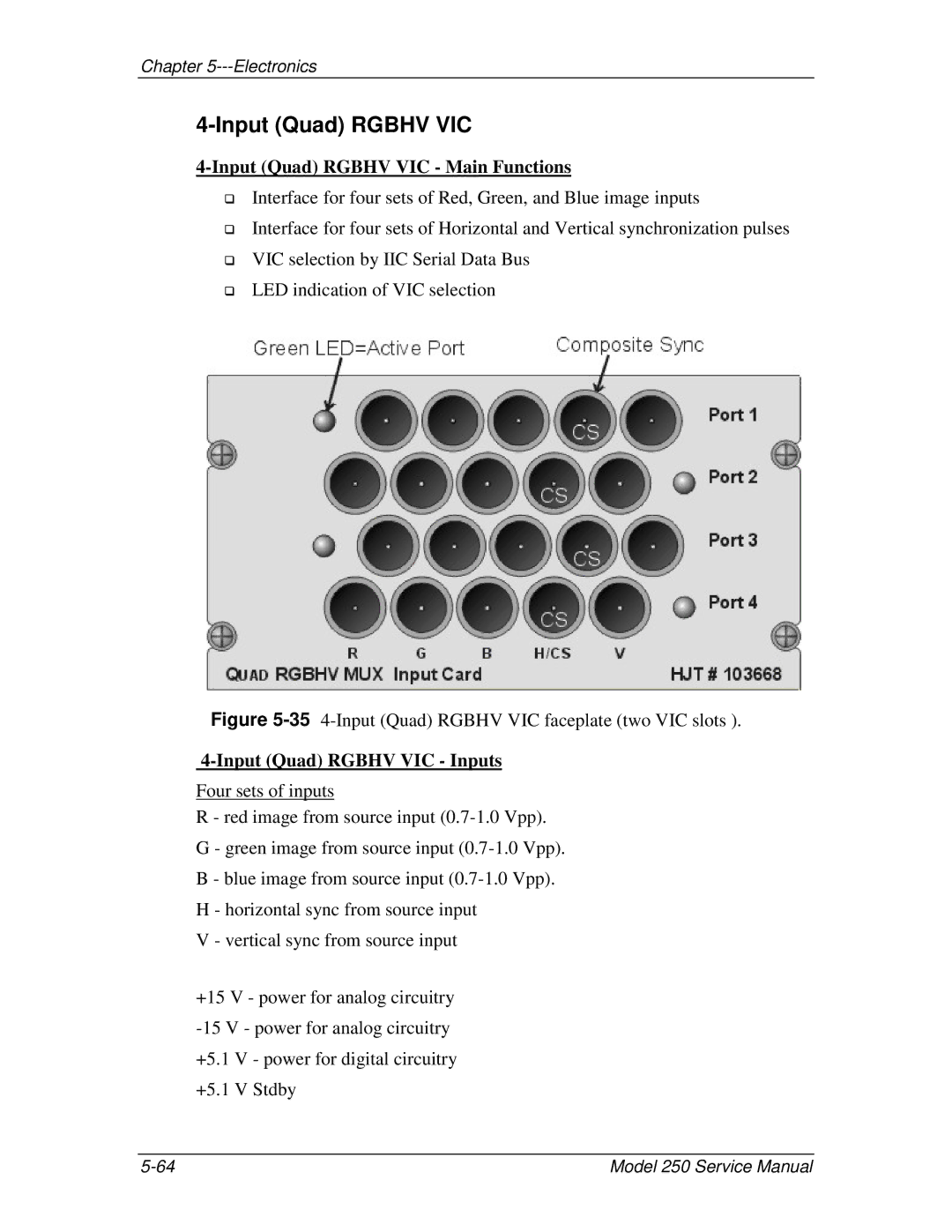
Figure 5-35 4-Input (Quad) RGBHV VIC faceplate (two VIC slots ).
4-Input (Quad) RGBHV VIC - Inputs
Four sets of inputs
R - red image from source input
G - green image from source input
B - blue image from source input
H - horizontal sync from source input
V - vertical sync from source input
+15 V - power for analog circuitry
Model 250 Service Manual |