Chapter 5---Electronics
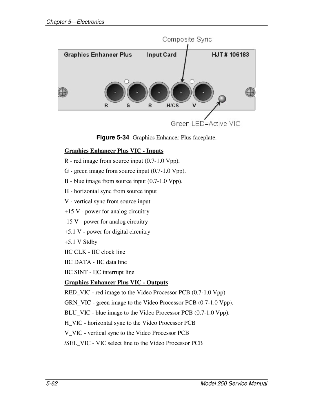
Figure 5-34 Graphics Enhancer Plus faceplate.
Graphics Enhancer Plus VIC - Inputs
R - red image from source input
G - green image from source input
B - blue image from source input
H - horizontal sync from source input
V - vertical sync from source input +15 V - power for analog circuitry
+5.1 V - power for digital circuitry
+5.1 V Stdby
IIC CLK - IIC clock line
IIC DATA - IIC data line
IIC SINT - IIC interrupt line
Graphics Enhancer Plus VIC - Outputs
RED_VIC - red image to the Video Processor PCB
V_VIC - vertical sync to the Video Processor PCB /SEL_VIC - VIC select line to the Video Processor PCB
Model 250 Service Manual |