Chapter 5---Electronics
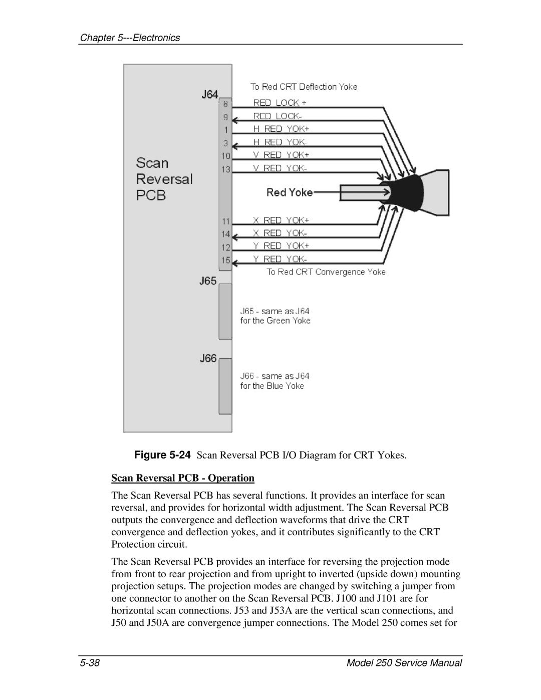
Figure 5-24 Scan Reversal PCB I/O Diagram for CRT Yokes.
Scan Reversal PCB - Operation
The Scan Reversal PCB has several functions. It provides an interface for scan reversal, and provides for horizontal width adjustment. The Scan Reversal PCB outputs the convergence and deflection waveforms that drive the CRT convergence and deflection yokes, and it contributes significantly to the CRT Protection circuit.
The Scan Reversal PCB provides an interface for reversing the projection mode from front to rear projection and from upright to inverted (upside down) mounting projection setups. The projection modes are changed by switching a jumper from one connector to another on the Scan Reversal PCB. J100 and J101 are for horizontal scan connections. J53 and J53A are the vertical scan connections, and J50 and J50A are convergence jumper connections. The Model 250 comes set for
Model 250 Service Manual |