Chapter 5---Electronics
Scan Reversal PCB - Service Adjustments
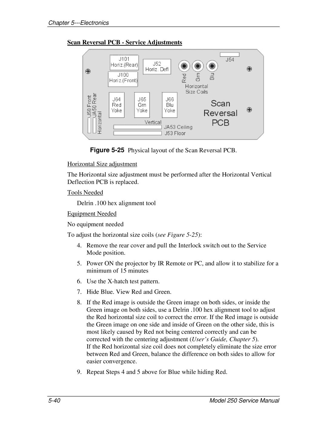
Figure 5-25 Physical layout of the Scan Reversal PCB.
Horizontal Size adjustment
The Horizontal size adjustment must be performed after the Horizontal Vertical Deflection PCB is replaced.
Tools Needed
Delrin .100 hex alignment tool
Equipment Needed
No equipment needed
To adjust the horizontal size coils (see Figure 5-25):
4.Remove the rear cover and pull the Interlock switch out to the Service Mode position.
5.Power ON the projector by IR Remote or PC, and allow it to stabilize for a minimum of 15 minutes
6.Use the X-hatch test pattern.
7.Hide Blue. View Red and Green.
8.If the Red image is outside the Green image on both sides, or inside the Green image on both sides, use a Delrin .100 hex alignment tool to adjust the Red horizontal size coil to correct the error. If the Red image is outside the Green image on one side and inside of Green on the other side, this is most likely caused by Red not being centered correctly and can be corrected with the centering adjustment (User’s Guide, Chapter 5).
If the Red horizontal size coil does not completely eliminate the size error between Red and Green, balance the difference on both sides to allow for easier convergence.
9.Repeat Steps 4 and 5 above for Blue while hiding Red.
Model 250 Service Manual |