Chapter 5---Electronics
5.12 Backplane PCB
The Backplane PCB is the spine of the Electronics Module. Every major electronic component in the Model 250 projector connects to and through the Backplane PCB. It is hidden in the inside of the Electronics Module (see Figure
Troubleshooting on the Backplane PCB
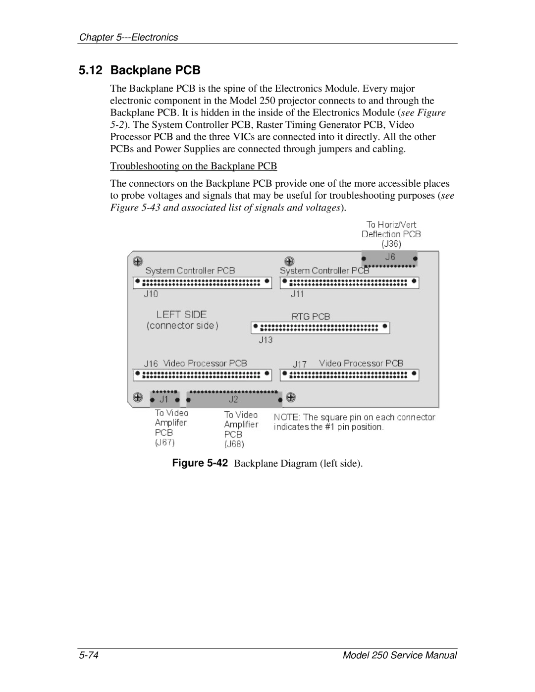
The connectors on the Backplane PCB provide one of the more accessible places to probe voltages and signals that may be useful for troubleshooting purposes (see Figure
Figure 5-42 Backplane Diagram (left side).
Model 250 Service Manual |