Chapter 5---Electronics
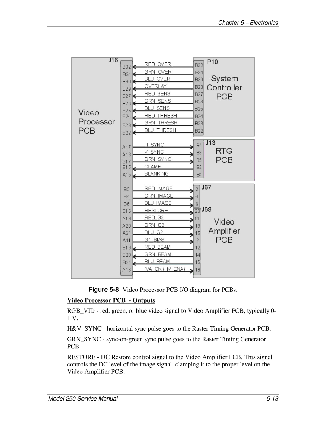
Figure 5-8 Video Processor PCB I/O diagram for PCBs.
Video Processor PCB - Outputs
RGB_VID - red, green, or blue video signal to Video Amplifier PCB, typically 0- 1 V.
H&V_SYNC - horizontal sync pulse goes to the Raster Timing Generator PCB.
GRN_SYNC -
RESTORE - DC Restore control signal to the Video Amplifier PCB. This signal controls the DC level of the image signal, clamping it to the proper level on the Video Amplifier PCB.
Model 250 Service Manual |
