same precautions for routing these wires that you followed for running the power and remote turn on wires. Cut off excess and, using wire strippers, strip
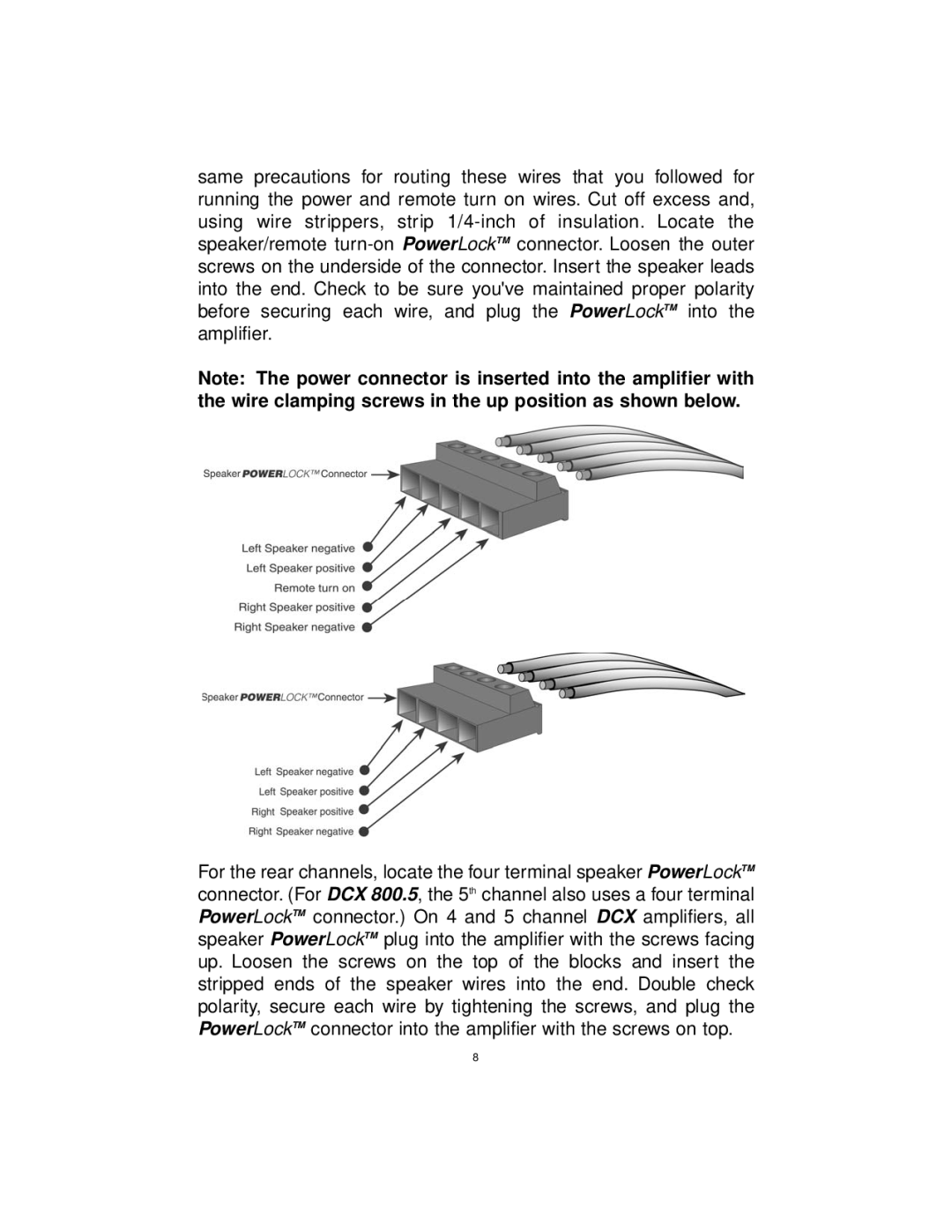
Note: The power connector is inserted into the amplifier with the wire clamping screws in the up position as shown below.
For the rear channels, locate the four terminal speaker PowerLockTM connector. (For DCX 800.5, the 5th channel also uses a four terminal PowerLockTM connector.) On 4 and 5 channel DCX amplifiers, all speaker PowerLockTM plug into the amplifier with the screws facing up. Loosen the screws on the top of the blocks and insert the stripped ends of the speaker wires into the end. Double check polarity, secure each wire by tightening the screws, and plug the PowerLockTM connector into the amplifier with the screws on top.
8