DCX 300.2, DCX 500.2 FRONT PLATE DIAGRAM
1211
DC X 300.2 DCX 500.2
FrontPanel
|
| R |
|
|
|
|
| R |
|
|
BR ID G E |
|
|
|
|
|
|
|
|
|
|
- | + |
| O UTPUT XOVER |
|
| G AIN |
|
| XOVER | |
|
|
|
|
| FREQ Q BASS | ATT |
|
|
| |
|
|
|
| LP |
|
|
|
|
| LP |
|
| L | 30 | 40k |
|
| M IN M AX | L | 30 | 40k |
R- R+ REM L+ | L- |
| O UTPUT FREQ FULL HP | 2 | 1 |
| INTPUT FREQ FULL HP | |||
|
|
|
|
|
|
| ||||
1 | 2 | 3 | 4 | 5 | 6 | 7 | 8 | 9 | 10 |
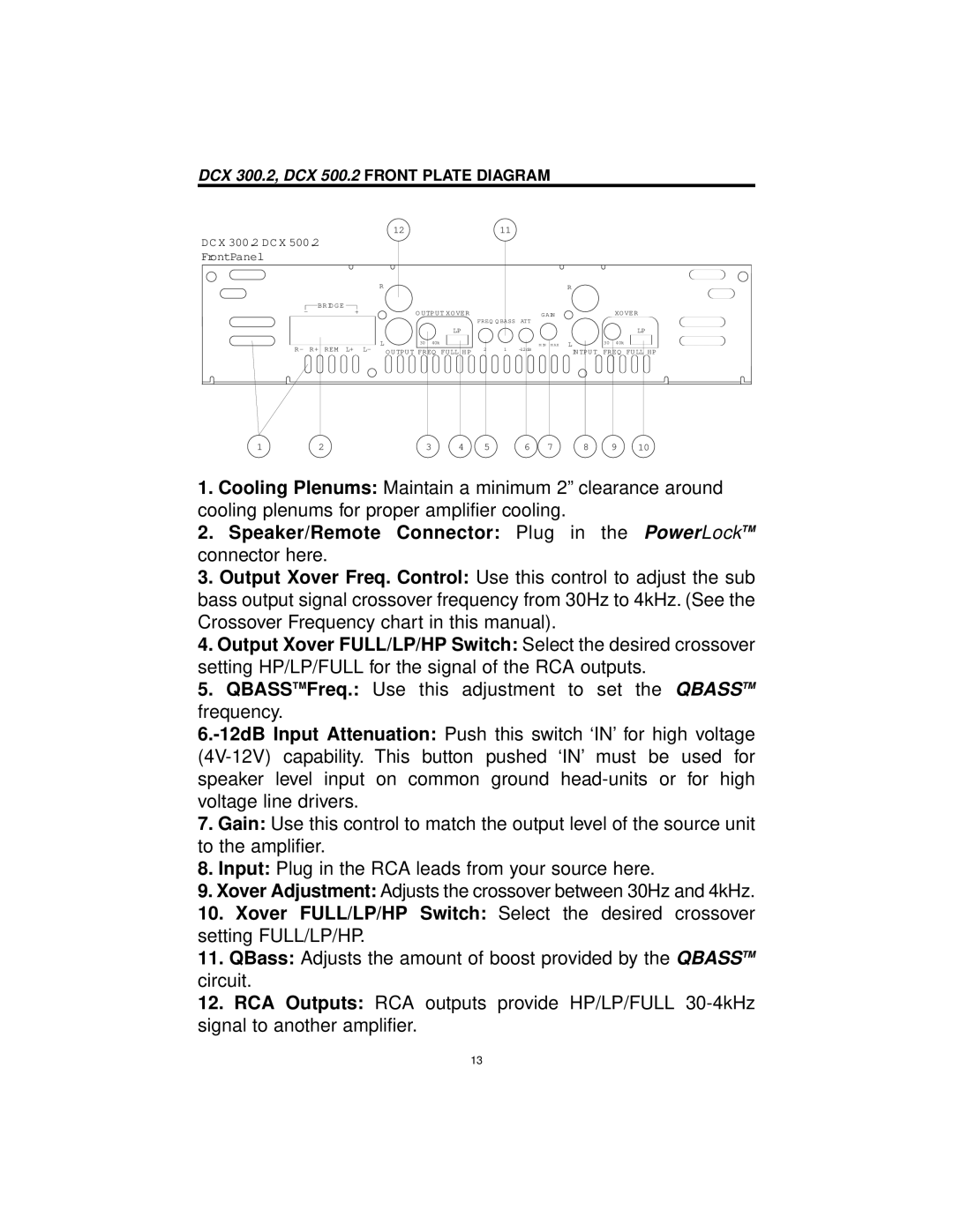
1.Cooling Plenums: Maintain a minimum 2” clearance around cooling plenums for proper amplifier cooling.
2.Speaker/Remote Connector: Plug in the PowerLockTM connector here.
3.Output Xover Freq. Control: Use this control to adjust the sub bass output signal crossover frequency from 30Hz to 4kHz. (See the Crossover Frequency chart in this manual).
4.Output Xover FULL/LP/HP Switch: Select the desired crossover setting HP/LP/FULL for the signal of the RCA outputs.
5.QBASSTMFreq.: Use this adjustment to set the QBASSTM frequency.
7.Gain: Use this control to match the output level of the source unit to the amplifier.
8.Input: Plug in the RCA leads from your source here.
9.Xover Adjustment: Adjusts the crossover between 30Hz and 4kHz.
10.Xover FULL/LP/HP Switch: Select the desired crossover setting FULL/LP/HP.
11.QBass: Adjusts the amount of boost provided by the QBASSTM circuit.
12.RCA Outputs: RCA outputs provide HP/LP/FULL
13