Precision Power PC1400 owner manual Speaker Wiring, Speaker/Remote PowerLock

Models: PC1400

1 23
Download 23 pages 23.25 Kb
Page 14
Image 14

SPEAKER WIRING

Using 14 gauge or larger, run the speaker wires from the amplifier location through the vehicle to the speakers. Observe the same precautions for routing these wires that you followed for running the power and remote
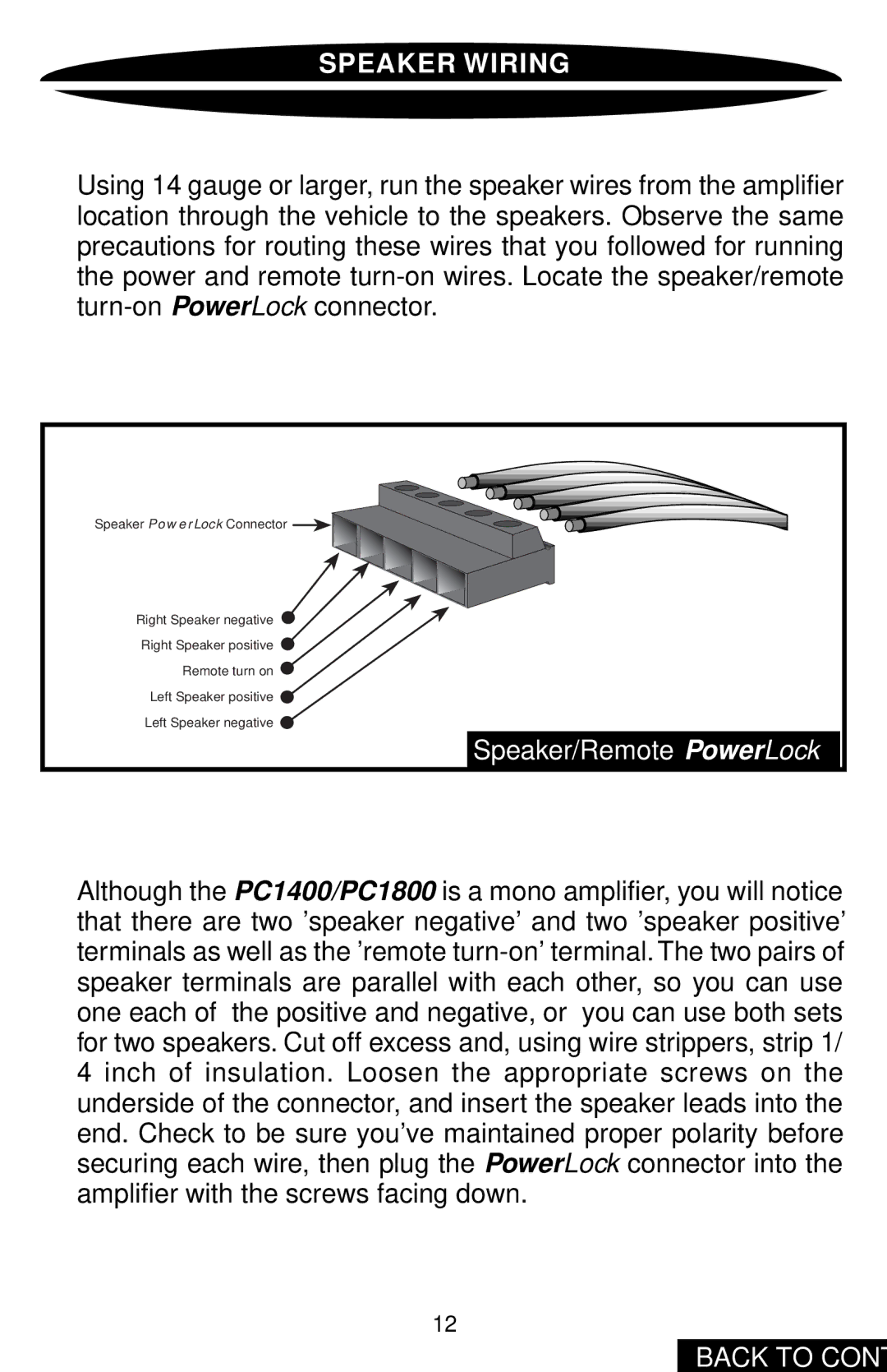
 turn-on wires. Locate the speaker/remote turn-on PowerLock connector.

Speaker PowerLock Connector

Right Speaker negative

Right Speaker positive

Remote turn on

Left Speaker positive

Left Speaker negative

Speaker/Remote PowerLock

Although the PC1400/PC1800 is a mono amplifier, you will notice that there are two 'speaker negative' and two 'speaker positive' terminals as well as the 'remote turn-on' terminal. The two pairs of speaker terminals are parallel with each other, so you can use one each of the positive and negative, or you can use both sets for two speakers. Cut off excess and, using wire strippers, strip 1/ 4 inch of insulation. Loosen the appropriate screws on the underside of the connector, and insert the speaker leads into the end. Check to be sure you've maintained proper polarity before securing each wire, then plug the PowerLock connector into the amplifier with the screws facing down.

12

BACK TO CONTENTS

Page 14
Image 14
Precision Power PC1400 owner manual Speaker Wiring, Speaker/Remote PowerLock